
Introduction to Microscopy
Microscopes are instruments designed to produce magnified visual or photographic images of objects too small to be seen with the naked eye. The microscope must accomplish three tasks: produce a magnified image of the specimen, separate the details in the image, and render the details visible to the human eye or camera. This group of instruments includes not only multiple-lens (compound microscopes) designs with objectives and condensers, but also very simple single lens instruments that are often hand-held, such as a loupe or magnifying glass.
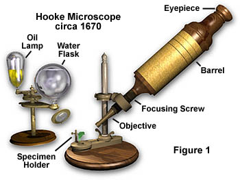
The microscope illustrated in Figure 1 is a simple compound microscope invented by British microscopist Robert Hooke sometime in the 1660s. This beautifully crafted microscope has an objective lens near the specimen and is focused by turning the body of the microscope to move the objective closer to or farther from the specimen. An eyepiece lens is inserted at the top of the microscope and, in many cases, there is an internal "field lens" within the barrel to increase the size of the viewfield. The microscope in Figure 1 is illuminated through the oil lamp and water-filled spherical reservoir, also illustrated in Figure 1. Light from the lamp is diffused when it passes through the reservoir and is then focused onto the specimen with a lens attached to the reservoir. This early microscope suffered from chromatic (and spherical) aberration, and all images viewed in white light contained "halos" that were either blue or red in color.
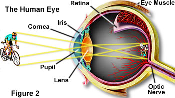
Since so many microscope users rely upon direct observation, it is important to understand the relationship between the microscope and the eye. Our eyes are capable of distinguishing color in the visible portion of the spectrum: from violet to blue to green to yellow to orange to red; the eye cannot perceive ultraviolet or infrared rays. The eye also is able to sense differences in brightness or intensity ranging from black to white and all the gray shades in between. Thus, for an image to be seen by the eye, the image must be presented to the eye in colors of the visible spectrum and/or varying degrees of light intensity. The eye receptors of the retina used for sensing color are the cone cells; the cells for distinguishing levels of intensity, not in color, are the rod cells. These cells are located on the retina at the back of the inside of the eye. The front of the eye (see Figure 2), including the iris, the curved cornea, and the lens are respectively the mechanisms for admitting light and focusing it on the retina.
For an image to be seen clearly, it must spread on the retina at a sufficient visual angle. Unless the light falls on non-adjacent rows of retinal cells (a function of magnification and the spreading of the image), we are unable to distinguish closely-lying details as being separate (resolved). Further, there must be sufficient contrast between adjacent details and/or the background to render the magnified, resolved image visible.
| Interactive Java Tutorial | |||||||||||
|
|||||||||||
Because of the limited ability of the eye's lens to change its shape, objects brought very close to the eye cannot have their images brought to focus on the retina. The accepted conventional viewing distance is 10 inches or 25 centimeters.
More than five hundred years ago, simple glass magnifiers were developed. These were convex lenses (thicker in the center than the periphery). The specimen or object could then be focused by use of the magnifier placed between the object and the eye. These "simple microscopes" could spread the image on the retina by magnification through increasing the visual angle on the retina.
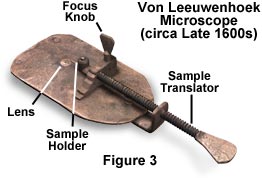
The "simple microscope" or magnifying glass reached its highest state of perfection, in the 1600's, in the work of Anton von Leeuwenhoek who was able to see single-celled animals (which he called "animalcules") and even some larger bacteria with a simple microscope similar to the one illustrated in Figure 3. The image produced by such a magnifier, held close to the observer's eye, appears as if it were on the same side of the lens as the object itself. Such an image, seen as if it were ten inches from the eye, is known as a virtual image and cannot be captured on film.
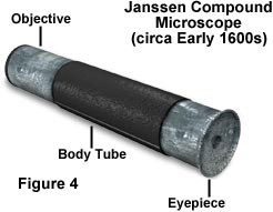
Around the beginning of the 1600's, through work attributed to the Janssen brothers (see the microscope in Figure 4) in the Netherlands and Galileo in Italy, the compound microscope was developed. In its simplest form, it consisted of two convex lenses aligned in series: an object glass (objective) closer to the object or specimen; and an eyepiece (ocular) closer to the observer's eye (with means of adjusting the position of the specimen and the microscope lenses). The compound microscope achieves a two-stage magnification. The objective projects a magnified image into the body tube of the microscope and the eyepiece further magnifies the image projected by the objective.
Compound microscopes developed during the seventeenth and eighteenth centuries were hampered by optical aberration (both chromatic and spherical), a flaw that is worsened by the use of multiple lenses. These microscopes were actually inferior to single lens microscopes of the period because of these artifacts. The images they produced were often blurred and had the colorful halos associated with chromatic aberrations that not only degrade image quality, but also hamper resolution. In the mid 1700's lens makers discovered that by combining two lenses made of glass with different color dispersions, much of the chromatic aberration could be reduced or eliminated. This discovery was first utilized in telescopes, which have much larger lenses than microscopes. It wasn't until the start of the 1800's that chromatically corrected lenses became commonplace in compound microscopes.
| Interactive Tutorial |
|
||||||||||
|
|||||||||||
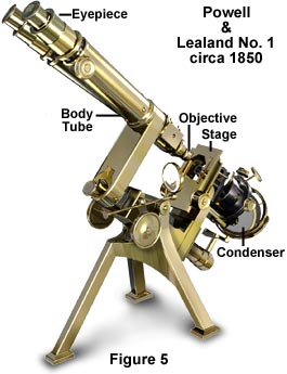
The eighteenth and nineteenth centuries witnessed a great improvement in the mechanical and optical quality of compound microscopes. Advances in machine tools allowed more sophisticated parts to be fabricated and, by the mid 1800's, brass was the alloy of choice for the production of high-quality microscopes. A number of British and German microscope manufacturers flourished during this time period. Their microscopes varied widely in design and production quality, but the overall principles defining their optical properties remained relatively constant. The microscope illustrated in Figure 5 was manufactured by Hugh Powell and Peter Lealand about 1850. The tripod base provided a sturdy support for the microscope, which many people consider the most advanced of its period.
By the end of the nineteenth century, there was a high degree of competition among microscope manufacturers and the development and production costs of microscopes became an important factor. Brass, the material of choice for microscope manufacturers, is very expensive and it was a lengthy task to machine, polish, and lacquer microscope bodies and other parts machined from this metal. To cut expenses, microscope manufacturers first started to paint the exterior portion of the microscope body and stand, as well as the stage and other non-moving parts.
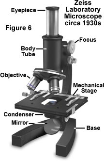
During the first quarter of the twentieth century, many microscope manufacturers had begun substituting cast iron for brass in microscope frames and stages. Iron was much cheaper and could be not be distinguished from brass when painted black. They also started to electroplate many of the critical brass components such as knobs, objective barrels, nosepieces, eyepieces, and mechanical stage assemblies (illustrated in Figure 6). These early twentieth century microscopes still subscribed to a common design motif. They were monocular with a substage mirror that was used with an external lamp to illuminate the specimen. A typical microscope of the period is the Zeiss Laboratory microscope pictured in Figure 6. This type of microscope is very functional and many are still in use today.
Modern microscopes far exceed the design specifications of those made prior to the mid 1900's. Glass formulations are vastly improved allowing greater correction for optical aberration than ever before, and synthetic anti-glare lens coatings are now very advanced. Integrated circuit technology has allowed manufacturers to produce "smart" microscopes that incorporate microprocessors into the microscope stand. Photomicrography in the late twentieth century is easier than ever before with auxiliary attachments that monitor light intensity, calculate exposure based on film speed, and automatically perform complicated tasks such as bracketing, multiple exposure, and time-lapse photography.
| Interactive Tutorial |
|
||||||||||
|
|||||||||||
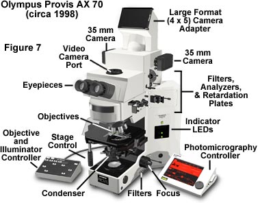
The microscope illustrated in Figure 7 is an Olympus Provis AX70 research microscope. This microscope represents the latest state-of-the-art design that incorporates multiple illuminators (episcopic and diascopic), analyzers and polarizers, DIC prisms, fluorescence attachments, and phase contrast capabilities. The photomicrography system is the ultimate in sophistication and performance featuring spot measurement, automatic exposure control, and zoom magnification for flexible, easy framing. The Y-shaped frame is designed to be user-friendly by offering the maximum in operator comfort and ease of use.
The previous discussion addressed the basic concept of what a microscope is and touched upon an abbreviated history beginning in the seventeenth century and progressing through modern times. There are a number of additional topics that are of paramount importance towards gaining a complete understanding of microscopes and microscopy. These topics will be discussed in subsequent sections of the primer.
Practically everyone has, at one time or another, viewed the world through an optical microscope. For most people, this experience occurs during biology training in high school or college, although some scientific entrepreneurs have purchased their own microscopes either individually or as part of a science kit. Photography through the microscope, or more commonly, photomicrography, has long been a useful tool to scientists. For many years, the biological and medical sciences have relied heavily on microscopy to solve problems relating to the overall morphological features of specimens as well as a quantitative tool for recording specific optical features and data. In this respect, the optical microscope has proven useful in countless investigations into the mysteries of life.
| Interactive Tutorial | |||||||||||
|
|||||||||||
More recently, microscopy has enjoyed an explosive growth as a tool in the physical and materials sciences as well as the semiconductor industry, due to the need to observe surface features of new high-tech materials and integrated circuits. Microscopy is also becoming an important tool for forensic scientists who are constantly examining hairs, fibers, clothing, blood stains, bullets, and other items associated with crimes. Modern advances in fluorochrome stains and monoclonal antibody techniques have heralded an explosive growth in the use of fluorescence microscopy in both biomedical analysis and cell biology.
| Interactive Tutorial |
|
||||||||||
|
|||||||||||
The basic differences between biomedical and materials microscopy involves how the microscope projects light onto the sample. In classical biological microscopy, very thin specimens are prepared and the light is passed or transmitted through the sample, focused with the objective and then passed into the eyepieces of the microscope. For observing the surface of integrated circuits (that comprise the internal workings of modern computers) light passed through the objective and is then reflected from the surface of the sample and into the microscope objective. In scientific nomenclature, transmitted and reflected light microscopy are known as diascopic and episcopic illuminated microscopy, respectively. The photomicrographs in our photo galleries are derived from both transmitted and reflected optical microscopic scientific investigations.
One of the most serious problems in microscopy is the poor contrast produced when light is passed through very thin specimens or reflected from surfaces with a high degree of reflectivity. To circumvent this lack of contrast, various optical "tricks" have been perfected by scientists to increase contrast and to provide color variations in specimens. The assortment of techniques in the microscopists bag include: polarized light, phase contrast imaging, differential interference contrast, fluorescence illumination, darkfield illumination, Rheinberg illumination, Hoffman modulation contrast, and the use of various gelatin optical filters. A thorough discussion of these techniques is provided in the Specialized Microscopy Techniques section of this primer. References are provided in both classical bibliographic form and as website links in the front-end page of the microscopy primer. These should serve to provide more details of microscopy and photomicrography to interested readers as well as links to additional material on the World Wide Web.
Contributing Authors
Mortimer Abramowitz - Olympus America, Inc., Two Corporate Center Drive., Melville, New York, 11747.
Michael W. Davidson - National High Magnetic Field Laboratory, 1800 East Paul Dirac Dr., The Florida State University, Tallahassee, Florida, 32310.
BACK TO ANATOMY OF THE MICROSCOPE