Interactive Java Tutorials
Polarization of Light
When light travels through a linear polarizing material, a selected vibration plane is passed by the polarizer, while electric field vectors vibrating in all other orientations are blocked. Linearly polarized light transmitted through a polarizer can be either passed or absorbed by a second polarizer, depending upon the electric vector transmission azimuth orientation of the second polarizing material. This tutorial explores the effect of rotating two polarizers on an incident beam of white light.
The tutorial initializes with red, green, and blue sine waves (simulating white light) originating from the left-hand side of the window and striking a linear polarizer (labeled Polarizer 1). This polarizer allows only light waves that are vibrating parallel to the transmission axis (oriented vertically) to pass. Polarizer 2 is initially positioned with its transmission axis parallel to that of polarizer 1, and also passes linearly polarized light transmitted through the first polarizer. To operate the tutorial, use the Angle 1 and Angle 2 sliders to adjust the orientation of the polarizers with respect to the incident white illumination (through a range of 360 degrees). When the slider bars are translated, the polarizers are rotated, affecting the transmission of light through the virtual polarizing system.
In linear polarizers, incident light waves having electric vector vibrations that are parallel to the crystal axis of the polarizer are absorbed. Many of the incident waves will have a vector orientation that is oblique, but not perpendicular to the crystal axis, and will only be partially absorbed. The degree of absorption for oblique light waves is dependent upon the vibration angle at which they impact the polarizer. Those rays that have angles close to parallel with respect to the crystal axis will be adsorbed to a much greater degree than those having angles close to the perpendicular. The most common Polaroid filters (termed the H-series) transmit only about 25 percent of the incident light beam, but the degree of polarization of the transmitted rays exceeds 99 percent.
A number of applications, most notably polarized optical microscopy, rely on crossed polarizers to examine birefringent or doubly refracting specimens. When two polarizers are crossed, their transmission axes are oriented perpendicular to each other and light passing through the first polarizer is completely extinguished, or absorbed, by the second polarizer, which is typically termed an analyzer. The light-absorbing quality of a dichroic polarizing filter determines exactly how much random light is extinguished when the polarizer is utilized in a crossed pair, and is referred to as the extinction factor of the polarizer. Quantitatively, the extinction factor is determined by the ratio of light that is passed by a pair of polarizers when their transmission axes are oriented parallel versus the amount passed when they are positioned perpendicular to each other. In general, extinction factors between 10,000 and 100,000 are required to produce jet-black backgrounds and maximum observable specimen birefringence (and contrast) in polarized optical microscopy.

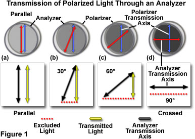
The amount of light passing through a crossed pair of high-quality polarizers is determined by the orientation of the analyzer with respect to the polarizer. When the polarizers are oriented perpendicular to each other, they display a maximum level of extinction. However, at other angles, varying degrees of extinction are obtained, as illustrated by the vector diagrams presented in Figure 1. The analyzer is utilized to control the amount of light passing through the crossed pair, and can be rotated in the light path to enable various amplitudes of polarized light to pass through. In Figure 1(a), the polarizer and analyzer have parallel transmission axes and the electric vectors of light passing through the polarizer and analyzer are of equal magnitude and parallel to each other.
Rotating the analyzer transmission axis by 30-degrees with respect to that of the polarizer reduces the amplitude of a light wave passing through the pair, as illustrated in Figure 1(b). In this case, the polarized light transmitted through the polarizer can be resolved into horizontal and vertical components by vector mathematics to determine the amplitude of polarized light that is able to pass through the analyzer. The amplitude of the ray transmitted through the analyzer is equal to the vertical vector component (illustrated as the yellow arrow in Figure 1(b)).
Continued rotation of the analyzer transmission axis, to a 60-degree angle with respect to the transmission axis of the polarizer, further reduces the magnitude of the vector component that is transmitted through the analyzer (Figure 1(c)). When the analyzer and polarizer are completely crossed (90-degree angle), the vertical component becomes negligible (figure 1(d)) and the polarizers have achieved their maximum extinction value.
The amount of light passing through a pair of polarizers can be quantitatively described by applying Malus' cosine-squared law, as a function of the angles between the polarizer transmission axes, utilizing the equation:
where I is the intensity of light passing through the analyzer (and the total amount of light passed through the pair of crossed polarizers), I(o) is the intensity of light that is incident upon the polarizer, and q is the angle between the transmission axes of the polarizer and analyzer. By examining the equation, it can be determined that when the two polarizers are crossed (q = 90 degrees), the intensity is zero. In this case, light passed by the polarizer is completely extinguished by the analyzer. When the polarizers are partially crossed at 30 and 60 degrees, the light transmitted by the analyzer is reduced by 25 percent and 75 percent, respectively.
Contributing Authors
Mortimer Abramowitz - Olympus America, Inc., Two Corporate Center Drive., Melville, New York, 11747.
Matthew J. Parry-Hill and Michael W. Davidson - National High Magnetic Field Laboratory, 1800 East Paul Dirac Dr., The Florida State University, Tallahassee, Florida, 32310.
BACK TO POLARIZED LIGHT MICROSCOPY
