
Polarized Light Microscopy
Introduction to Biological
Polarization Microscopy
(Part 2)
In order to strengthen and apply the principles discussed in part one to the polarizing microscope for the study of biological material, we turn our attention to the determination of crystalline axes. For this effort, another demonstration using two pieces of plastic sheet polarizing material is appropriate, as discussed below.
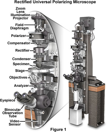
Before embarking on a discussion of the principles behind the polarized light microscope, we review a state-of-the-art instrument designed specifically to image very weakly birefringent biological specimens. Presented in Figure 1 is a rectified universal polarizing microscope designed by Shinya Inoué, Gordon W. Ellis, and Edward Horn. The components, in eight units, are mounted on slides that ride on a high-precision, 3-inch dovetail, which stands four feet tall. The well-aged cast iron (Mehanite) dovetail bench is mounted on a horizontal axis and can be utilized vertically, horizontally, or at angles in between. Two smaller dovetails, built into the same casting, run precisely parallel to the central dovetail and provide added flexibility (micromanipulators, ultraviolet microbeam source, etc. are mounted on these dovetails). Supported on the sturdily built wooden bench, by the horizontal axis near the center of gravity of the massive optical bench, and designed for semikinematic support of the components wherever practical, the microscope is quite immune to vibration.
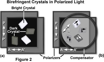
Returning to a simple polarized light model, construction is based on two square Polaroidä sheets placed in front of a diffuse light source and oriented at right angles to each other so that the light is extinguished. Next, a suitable birefringent sample is inserted between the crossed polars, as is done with a conventional polarizing microscope. As an example, when a piece of cellophane is placed between crossed polars, light is seen through that area (Figure 2(a)). The phenomenon is due to birefringence, as explained below, even though a double image is not observed.
Determination of Crystalline Axes
As demonstrated in Figure 2(a), birefringent crystals appear bright when viewed through crossed polarizers, depending upon their orientation with respect to the vibration planes of light passing through the individual polarizers. In the example, polarizer transmission, PP', and analyzer transmission, AA' are oriented at 90 degree angles to each other and extinguish the background light. When the crystals are viewed between the polarizers with its optical axes parallel to PP' or AA', the crystal is dark. With the axes in any other orientation, the crystals are brighter.
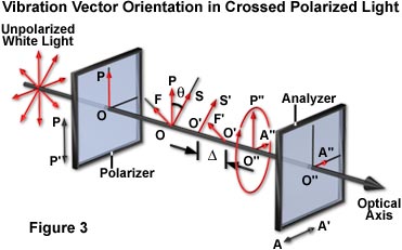
A schematic diagram explaining the phenomenon of birefringence demonstrated by crystals placed between crossed polarizers is presented in Figure 3. Light having an amplitude of OP and the electric vector oriented parallel to the polarizer transmission direction (PP') vibrates vertically. Upon entering the birefringent crystal, OP is vectorially split into two vibrations, OS and OF, which represent the slow and fast wave, respectively. These vibration directions are uniquely defined by the crystalline structure of the specimen because they lie in the directions of the major and minor axes of the index ellipse. In the crystal (cellophane in this example), these two waves travel at different velocities so that when they emerge from the crystal (as O'S' and O'F'), they are out of phase relative to each other. The degree of phase shift is expressed as D, or fractions of a wavelength (of the monochromatic light wave in air; l(o)), and is proportional to the thickness of the crystal (d) and to its coefficient of birefringence, which is represented by (n(e) - n(o)), and expressed as:
D = (ne - no) d/ lo |
(1) |
where n(e) is the refractive index for the extraordinary ray, and n(o) that of the ordinary ray. The e-ray may either be the slow or fast wave depending on the crystal type. If the e-ray is the slow wave (as it is in quartz and cellophane), the crystal is said to be positively birefringent. However, if the e-ray is the fast wave (as it is in calcite), the crystal is said to be negatively birefringent. The Fresnel ellipsoid for a positively birefringent material is prolate, while the one for a negatively birefringent material is oblate. The combination of the two waves, which remain out of phase and continue to oscillate in planes perpendicular to each other in the air, yields an elliptical polarized wave (O"P"O"A").
Light that is elliptically polarized no longer vibrates only along the PP' axis, because it has a component (O"A") that exists along the AA' axis. This component of the elliptically polarized light can pass through the second polarizer or analyzer, giving rise to the observed light.
For a birefringent specimen between crossed polars, the elliptically polarized wave is produced by splitting the original plane-polarized wave into two vectors. If one of the two vectors is missing, elliptical polarization is not obtained. This occurs when the slow or fast specimen axes become oriented parallel to the polarizer axis. At that orientation of the crystal, OP' cannot be split into two vectors, so OP' emerges from the crystal unaltered. This wave is completely absorbed by the analyzer and no light is transmitted. Therefore, by rotating a specimen placed between crossed polars, the crystalline axes can be determined by noting when the specimen turns dark (see Figure 2(a)). When the specimen turns dark between crossed polars, the orientations of the major and minor axes of the index ellipse are parallel to the axes of the polars. Note that these axes may or may not coincide with the geometrical axes or cleavage planes of the specimen.
| Interactive Java Tutorial | |||||||||||
|
|||||||||||
Although the two orthogonal axes in the crystal can be easily determined with crossed polarizers, it is impossible to distinguish between the fast and slow axes with only simple linear polarizers. In order to determine individual axis identities, a compensator (a crystalline material with known slow and fast axes) is added to the light path with the specimen between crossed polarizers.
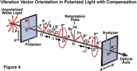
Compensator action in the polarized light model can be demonstrated with a piece of plastic having previously identified slow and fast axes. The compensator is superimposed over an specimen with unknown axes (illustrated in Figure 2(b)), and both are placed between a pair of crossed polarizers. If the slow axis of the compensator and that of the unknown specimen lie perpendicular to each other, then the two effects cancel each other out, extinguishing the light, and making the specimen appear dark (as is the crystal in the lower right portion of Figure 2(b)). What has happened is that the elliptically polarized light produced by the specimen is restored by the compensator to the original plane-polarized light (Figure 4). Therefore, no vectorial component is present in the analyzer transmission direction, so that all light is absorbed by the analyzer.
The compensator, illustrated as a large circle in Figure 2(b), introduces some light between the crossed polars. On this gray background, the crystal appears darker (the lower right orientation) when the s axis is in the opposite quadrant from the s axis of the compensator, termed subtractive orientation (see Figure 4). Complete extinction occurs when conditions in equations (2) or (3) (below) are satisfied. When the crystal and compensator s axes are in the same quadrant (the top orientation in Figure 2(b)), the crystal appears considerably brighter than the gray background. The contrast of the crystal against the gray background disappears when the axes of the crystal coincide with PP' and AA".
Under conditions where both the specimen and the compensator slow axes are parallel to each other, the two retardations will add together, and more light passes through the analyzer (top orientation of crystal in Figure 2(b)). By finding the orientation of the compensator that extinguishes or increases light from a birefringent specimen, the slow and fast axis directions of the specimen can be determined.
Quantitatively, extinction occurs when:
sin(D/2) sin 2(q) = -sin (Rc/2) sin 2(qc) |
(2) |
where D and R(c) are the retardances of the specimen and the compensator, respectively, expressed in degrees of arc (1l = 360 degrees), and q and q(c) are respectively the angle between the slow axes of the specimen and of the compensator relative to OP, the polarizer transmission direction (Figure 4). Equation (2) is used extensively for the photographic photometric analysis of retardance and azimuth angles of DNA microcrystalline domains in cave cricket sperm. If the specimen is oriented so that q = 45 degrees ± 5 degrees, and neither D nor R(c) are greater than 20 degrees, or less than approximately l/20 then, to a very close approximation, the equation can be simplified to:
D = Rc sin 2(qc) |
(3) |
This is the principle used for measuring specimen retardance with the Brace-Köhler compensator.
It is important not to confuse birefringence with optical rotation, which is a phenomenon that would be encountered when, for example, a sugar solution is substituted for the crystalline specimen (or if a quartz crystal was observed along the optical axis, the axis of symmetry). A solution of sugar has no directionality, but it can twist polarized light in a left-handed or right-handed direction, depending on its chemical nature. The result is similar to turning the polarizer PP', so that the light can then be extinguished by turning the analyzer AA' by that same amount. With birefringence, however, the light cannot generally be extinguished by rotating the analyzer, as it can with optical rotation under monochromatic light. Optical rotation reflects the three-dimensional asymmetry of the individual molecules, which can be randomly oriented as in the case of a sugar solution. The phenomenon of Dispersion, a variation in refractive index with different wavelengths of light, is usually very substantial for optical rotation, but practically negligible for birefringence.
Molecular Structure and Birefringence
Molecular and micellar structure can be correlated with optical and mechanical anisotropy. For example, a thin sheet of polyvinyl alcohol (PVA) can easily be produced by casting a hot water solution of the polymer onto a clean piece of glass. The basic structure of PVA (illustrated in Figure 5) is that of a long, linear polymeric chain of repeating ethyl alcohol units. Molecular orbital configuration enables rotation around the carbon-carbon backbone bonds and the formation of randomly shaped strands from chain folding, except where adjacent chains lie in close proximity parallel to each other and they form a minute crystalline domain or micelle.
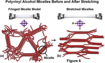
In a cast (dried gel) sheet of polyvinyl alcohol viewed normal to the surface, the polymers and their micelles would be expected to have a helter skelter arrangement (Figure 6(a)). Such a structure would be optically isotropic, as can be determined by the lack of birefringence (no light passes the cast PVA sheet placed between crossed polarizers at any orientation). Such a structure should also be mechanically isotropic and difficult to tear in any direction, since covalent molecular backbones traverse in every direction. This property makes cast sheets of polyvinyl alcohol very tough.
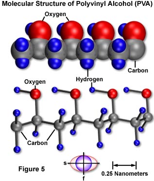
Figure 6(a) presents a model of the fringed micelle structure of a cast gel of polyvinyl alcohol viewed from the face. The circle to the right indicates a micelle where several PVA molecules run parallel and form a minute crystalline region. The micelles, and the polymer chains of PVA in between, are randomly oriented. The structure is isotropic as indicated by the index ellipse drawn beneath the micelle model. Also illustrated in the figure is the stretching action of a polyvinyl alcohol film. Above the micelle model a thin rectangular sheet of isotropic PVA is supported on both ends, clamped by two binders. Figure 6(b) illustrates the sheet after mild heating and stretching. The stretched portion becomes optically anisotropic (birefringent) with the slow axis oriented in the stretch direction. It is also mechanically anisotropic and tends to split parallel to the stretch direction.
Also presented in Figure 6(b) are fringed micelles in stretched polyvinyl alcohol. As manifested in the optical and mechanical anisotropy, the fringed micelles and the PVA molecules in general have become aligned with their long axes parallel to the stretch direction. The stretched film is highly birefringent and produces several wavelengths of retardation as seen from its color between crossed polars. In spite of the strong birefringence, light is extinguished when the film is oriented with its stretch direction parallel to the axis of the crossed polars.
Interference colors arise from white light composed of various wavelengths, where the thickness (d) of the crystal (See Equation (1)) gives rise to a full-wavelength retardation [n(e) - n(o)d = Nl(o) where N = 1,2,3....] that varies with l(o). When the retardation equals Nl(o), the light exciting the crystal returns to a plane-polarized wave identical to the one before it entered the crystal. Here it is extinguished by the analyzer and that wavelength is missing from the light transmitted through the analyzer. The result is a series of interference colors, or white minus that wavelength, from strongly birefringent specimens observed between crossed polars in white light.
Compensation reveals that it is the slow vibration axis that lies parallel to the stretch direction in dried polyvinyl alcohol films. This agrees with the molecular polarizability expected in PVA. In a polymer, with a covalently linked backbone and with small side groups, as is the case for PVA, the polarizability (or the dielectric constant) is considerably greater parallel to the covalent chain backbone than across it. As the side groups become larger, or if there are side groups with greater polarizabilities, which are often associated with light-absorbing conjugated bonds, the birefringence of the polymer becomes weaker, and can even reverse in sign. For example, the degree of nitration of nitrocellulose is monitored by observing its birefringence, which changes from positive to zero to negative as nitration increases. The birefringence of DNA is strongly negative.
A striking mechanical anisotropy of the stretched film of PVA also reflects the micellar and molecular arrangements. The film is even tougher than before and proves to be more resilient when tears across its stretch direction are attempted. However, in response to a rap on the tautly held film, it readily splits into strips parallel to the stretch direction (see Figure 6(b)).
The mechanical and optical anisotropies and the directions of their axes reflect the arrangements and anisotropic properties of the underlying molecules. In some biological samples, the molecules may take on a more complex arrangement than the homogeneous distribution seen in the PVA model. Nevertheless, the dielectric and optical properties specific to the particular molecular species provide important clues regarding the biological fine structure.
As an example, in a protein molecule with extended chains in the b-form, or with a collagen helix, the slow axis lies parallel to the long axis of the polypeptide chain and the molecular polarizability is considerably greater in that direction than across the chain.
In the B-form DNA, the slow axis is perpendicular to the backbone of the Watson-Crick double helix. The conjugated purine and pyrimidine bases exhibit a greater ultraviolet absorbance and electrical polarizability in the heterocyclic nitrogen base plane than perpendicular to the planes. Because the planes in B-form DNA are oriented at right angles to the molecular backbone, they show a characteristic ultraviolet negative dichroism and strong negative birefringence.
Lipids, in contrast, have the slow birefringence axis parallel to the molecular backbone. But since they tend to make layered sheets with the molecular axes lying perpendicular to the plane of the sheets, the layered structure also introduces form birefringence. Form birefringence, also known as textural birefringence, arises when platelets or rodlets of submicroscopic dimensions are stacked. The platelets or rodlets must be regularly aligned with spacings that are considerably smaller than the wavelength of light. Such bodies generally exhibit anisotropy of electrical polarizability and therefore of refractive index. The anisotropy is stronger with greater differences of refractive index between the medium interspersing the rodlets or platelets and the rodlets or platelets themselves. The anisotropy disappears or becomes weakest when the refractive index of the medium matches that of the rodlet or platelet. Form birefringence is due to the shape and orientation of molecules or molecular aggregates, and is independent of the birefringence that is intrinsic to the constituent molecules themselves. In contrast to form birefringence, the value of intrinsic birefringence usually does not change with the refractive index of the imbibing medium.
In form birefringence of platelets, the slow axis is parallel to the plane of the plates. The axis of symmetry is perpendicular to the plates, and hence platelet-form birefringence always has a negative sign. This is due to the greater refractive index perpendicular to the axis of symmetry (the refractive index experienced by extraordinary light waves is less than that suffered by ordinary light waves). Lipid bilayers, or multilayers in the Schwann sheath of myelinated nerve, demonstrate a combination of intrinsic positive and form negative birefringence. Depending on the refractive index of the imbibing medium, the negative-form birefringence of the plates may become so strong as to overcome the intrinsic positive birefringence of the lipid molecules.
In contrast to platelet-form birefringence, form birefringence of rodlets is positive. Positive-form birefringence is also observed in microtubules, which are thin, elongated structures approximately 24 nanometers in diameter, made up of rows of globular protein molecules approximately 5 nanometers in diameter. In addition, actin, a twisted double cable of globular protein molecules, displays positive-form birefringence due to low molecular asymmetry.
The Polarizing Microscope
The principles that have been reviewed in this discussion provide the basis for analyzing molecular arrangements and cellular fine structure with the polarizing microscope. A polarizing microscope is nothing more than an ordinary microscope equipped with a polarizer underneath the condenser, an analyzer above the objective, and somewhere in the path, in a convenient location between the polarizer and analyzer, a compensator (Figure 7). The compensator can be inserted before or after the specimen, which is usually supported on a 360-degree rotatable stage. In principle, that is all there is to a polarizing microscope.
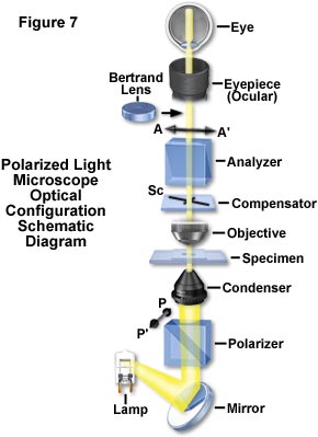
Reviewing the conventional polarizing microscope as illustrated in the schematic drawing presented in Figure 7, the polarizer is commonly oriented with its transmission axis (PP'), North-South with respect to the observer. The analyzer is oriented East-West (AA'). A Bertrand lens converts the ocular into a telescope and enables an image of the objective lens rear aperture to be observed. This provides a conoscopic image of the specimen, showing the interference pattern of convergent polarized light passing through the specimen at different angles. The Fraunhofer diffraction pattern produced by the specimen is also visible. With the Bertrand lens removed from the light path, the polarizing microscope produces a regular or orthoscopic image.
If cytoplasmic or nuclear structure is studied with a standard polarizing microscope (borrowed from a crystallographer or mineralogist), the results will be disappointing. Other than a few crystalline inclusions, little of interest in seen in a living cell. One reason is that the amount of light that strays through an ordinary polarizing microscope between crossed polars often cannot be reduced enough to see the weak birefringence exhibited by the filaments and membranes of interest.
The degree that the field can be darkened is expressed quantitatively as the extinction factor, which is defined as:
EF (Extinction Factor) = Ip ÷ Is |
(4) |
where I(p) is the intensity of light that passes through a polarizing device when the polarizer and analyzer transmission directions are parallel, and I(s), the minimum intensity that can be obtained when the polarizer and analyzer are crossed. For an ordinary polarizing microscope, the extinction factor is often of the order of 1,000 or even lower with high numerical aperture objectives. For cell study, an extinction factor of at least 10,000 is required.
In order to achieve this high an extinction factor, a number of conditions must be obtained concurrently. The polarizer and analyzer must be of good optical quality. They can be constructed of selected sheet Polaroidsä, as far as the extinction goes, but will have low transmittance and the rippled surface can deteriorate the image. Strained optical elements placed between the polars will not be sufficient. As seen by stressing a piece of glass or plastic between cross polars, the strain induces birefringence. This artifactual birefringence can be much higher than the specimen birefringence. Therefore, it is important to use lenses, slides, and coverslips that are free from strain. A little speck of airborne lint, possibly originating from our clothing or some lens tissue, can be highly birefringent, so it is very important to keep the microscopic system meticulously clean. Also, because almost all the light is extinguished by the analyzer, the light source must be very bright while remaining harmless to the specimen. Working in a darkened work area improves the sensitivity of the human eye. Alignment of the optical components is critical and Köhler illumination must be used to gain maximum field brightness while minimizing the amount of stray light.
The reason for all of this care is that the light that originates from the specimen is only a minute fraction of the original light. If D is the retardance of the specimen and q its azimuth orientation (both expressed in degrees), the luminance (I) due to specimen birefringence (D) is given by:
I = Ip · sin 2 D/2 |
(5) |
where I(p) is the luminance of the field with the polarizer and analyzer transmission parallel. I turns out to be of the order of 0.0001 to 0.000001 x I(p) for the range of specimen retardations of interest. This type of microscopy may be analogous to observing starlight during the daytime, in effect, trying to observe very dim light from the specimen in a relatively bright field. The specimen light is present, but there is so much more light surrounding the specimen that it cannot be seen without dramatically increasing the extinction factor and improving specimen contrast.
Exceptional use a compensator will improve the situation. This point can be demonstrated by placing a weakly birefringent specimen that is barely visible between crossed polars. The birefringent region is not significantly brighter than the background. Introduction of the compensator will make the background gray and the specimen either darker or much brighter than the background. In the presence of the compensator, the image brightness and the contrast can be vastly improved and images of weakly birefringent objects more easily displayed clearly (as demonstrated in Figures 8 and 12).
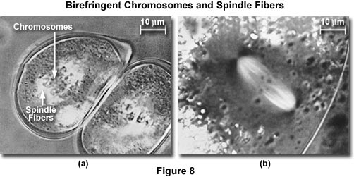
The mitotic apparatus images presented in Figure 8 are an excellent example of how compensation plates can improve observation of weakly birefringent biological specimens. In Figure 8(a), living pollen mother cells of Easter lily (Lilum longiflorum) are shown undergoing mitosis. Spindle fibers demonstrate stronger birefringence adjacent to kinetochores (the spindle fiber attachment point) of helical chromosomes, which display little birefringence. Another example is birefringent spindle fibers in a living oocyte of marine worm (Chaetopterus pergamentaceus; Figure 8(b)). Chromosomal spindle fibers are white with the astral rays, oriented at right angles to the spindle axis, being very dark. The maximum retardance of the spindle in Figure 8(a) is less and one-hundredth of a wavelength, while that shown in Figure 8(b) is about 3.5 nanometers.
Rectification
An additional improvement, rectification is required for detecting weakly birefringent specimens at high resolution in polarized microscopy. Following the Rayleigh equation for optical resolution, high objective and condenser numerical apertures are necessary to achieve high resolving power. However, each time the numerical aperture is increased by 0.2, stray light increases tenfold, even when using strain-free lenses. With objective and condenser numerical apertures at 1.25, the extinction factor may drop to nearly 100. This lowered extinction (with increased stray light) at high numerical aperture is due to the rotation of the plane of polarization at every oblique-incidence interface between the polarizer and the analyzer. It is an inherent physical optical phenomenon that was considered uncorrectable until the polarization rectifier was developed (see Figure 9).
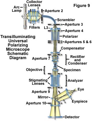
Figure 9 presents a schematic illustration of the optical path in a transilluminating, universal polarizing microscope designed to provide maximum sensitivity and superior image quality. The system is inverted with a light source on top and detectors at the bottom. Light from a high-pressure arc lamp is filtered (to remove infrared and provide monochromatic illumination) and focused by the collector lenses into a fiber-optic light scrambler. The fiber scrambles the image of concentrated mercury arc and provides a uniform circular patch of light that acts as the effective light source at Aperture 3. This source, projected by the zoom lens is made to just fill the condenser aperture diaphragm.
Illuminance of the field can be regulated without affecting the cone angle of illumination (or disturbing the color temperature in white light) by adjusting the first aperture in the light path. The polarizing Glan-Thompson prism is placed behind Aperture 5 away from the condenser to prevent light scattered by the polarizer from entering the condenser. Half-shade and other special plates are placed at the Aperture 6 level, and compensators above the condenser. Depolarization by rotation of polarized light in the condenser and objective lenses, slide, and coverslips are corrected by the rectifier. The image of the field diaphragm is focused on the specimen plane by the condenser, whose numerical aperture can be made equal to that of the objective. Stigmatizing lenses, which minimize the astigmatism that is otherwise introduced by the calcite analyzer, are low-reflection coated on their exterior face and cemented directly onto the analyzing Glan-Thompson prism to protect the delicate surfaces of the calcite prism. Aperture stops placed at critical points serve to minimize scattered light from entering the image-forming system. The final image is directed onto a sheet of photographic film, a video camera tube, or another sensor (a photomultiplier or CCD camera system). The image is observed via the mirror and oculars (eyepieces). All components between the scrambler and the detector are aligned on a single optical axis to minimize degradation of the image.
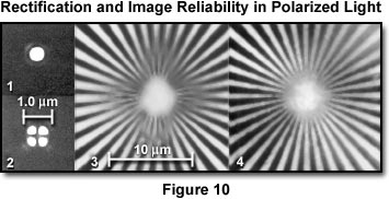
The effect of rectification on image reliability in the polarizing microscope is presented in Figure 10. In section (1) the Airy disk diffraction pattern of a pinhole viewed through crossed polarizers is displayed from a rectified polarizing microscope having an objective and condenser numerical aperture of 1.25. The pattern is identical with that obtained by a microscope in non-polarized light. Section (2) demonstrates the Airy disk with non-rectified lenses between crossed polarizers. The diffraction pattern is anomalous, and each bright point in the specimen is represented in the image by a bright four-leaf clover pattern surrounding a dark cross. A Siemens test star image is presented in section (3) when viewed between crossed polarizers in the absence of rectification. Contrast is reversed and spurious toward the center of the image. Section (4) presents the same test pattern viewed with the same optics after rectification. The aperture function of the lens is now uniform and the diffraction anomaly has disappeared.
The extinction is very good up to high numerical apertures with the rectifier, and the polarizing microscope is capable of providing quality images of weakly retarding specimens at the theoretical limit of microscopic resolution. Diffraction image errors, which may be present without rectification, are also corrected with the rectifier (Figure 10).
As demonstrated in Figure 10, rectification corrects for the diffraction error that is introduced by conventional lenses when low-retardation objects are observed between crossed polarizers. However, the sensitivity for detecting weak retardations at high resolution is so improved by rectification that another hitherto unnoticed optical phenomenon becomes apparent. At the edges of any specimen, including isotropic materials, light is diffracted as though each edge were covered with a double layer of extremely thin, birefringent material. The slow axis on the high index side is parallel to the edge, while that on the low index side is perpendicular. This phenomenon is termed edge birefringence. It is found at all sharp boundaries (edges) whether the two sides of the boundary are solid, liquid, or gas, so long as there exists a refractive index difference on the two sides of the boundary. It is clearly not based on the presence of a membrane at the optical interface, but is a basic diffraction phenomenon occurring at every edge. The electric vectors parallel and perpendicular to the edges must contribute to diffraction in a slightly asymmetric way on both sides of the edge and give rise to edge birefringence. Edge birefringence disappears when the refractive indices on both sides of the boundary are matched. It reverses in sign when the relative magnitude of refractive indices on the two sides of a boundary are reversed.
This behavior of edge birefringence is distinct from form birefringence. Form birefringence becomes zero (reaches a minimum value for rodlets, or maximum absolute value for platelets) when the refractive index of the immersion medium matches that of the rodlets or platelets, but then rises again (parabolically) when the refractive index of the immersion medium exceeds the match point.
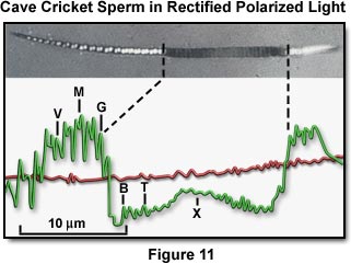
The improvements achieved with the rectified polarizing microscope make possible the determination of the complex alignment of DNA molecules in each unit diffraction area of live insect sperm (Figures 11 and 12). The birefringence and azimuth orientation of each DNA microdomain are measured (both to a precision of 0.1 degree) from microdensiometer traces (Figure 11) by correlating the traces taken at several compensator settings and stage orientations. The changes in birefringence and azimuth angles, following polarized ultraviolet microbeam irradiation (which selectively abolishes the birefringence contribution by those bases that absorbed the ultraviolet) reveal the helical packing arrangement of the DNA molecules within the microdomains.
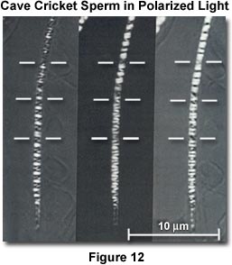
Figure 11 presents a photomicrograph of a living cave cricket sperm under a rectified polarizing microscope, with a densitometer trace of the image. The broad dark band in the middle of the sperm (where the densitometer trace dips below the background level) is where the birefringence of the DNA bases was selectively perturbed by irradiation with a polarized ultraviolet microbeam. The compensator is in the subtractive orientation so that the sperm head is darker than the background except where the specimen retardation is greater than the compensator (especially at the small dumbbell-shaped white patches, which give rise to the M shapes on the densitometer trace). In these regions, the birefringence and optical axes of the microcrystalline domains of the sperm DNA are such as to overcome the subtractive effect of the compensator.
The effect of three different settings of a mica compensator on the cave cricket sperm head is illustrated in Figure 12, using the rectified polarizing microscope. The detailed distribution of intrinsic birefringence in these chromosomes is demonstrated with great clarity in the specimen when it is immersed in dimethylsulfoxide (refractive index of 1.475). The horizontal white bars are helix breaks that correspond to the chromosome ends. Prior to these studies, few chromosomes had been observed from the mature sperm of any species.
Thus, the rectified polarizing microscope offers many unique opportunities for studying molecular organization, and its changes, in a single living cell undergoing physiological activities and developmental changes.
Author
Shinya Inoué - Marine Biological Laboratory, 7 MBL Street, Woods Hole, Massachusetts 02543.
BACK TO POLARIZED LIGHT MICROSCOPY