Fluorescence Microscopy
Transmitted Light Illumination
The early fluorescence microscope utilized transmitted light illumination (diascopic fluorescence). A primary filter to select the excitation light wavelengths was placed in the light port of the microscope and a secondary barrier filter was positioned above the microscope nosepiece to block residual excitation light and to select emission wavelengths reaching the eye or camera.

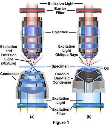
The optical pathways illustrated in Figure 1 represent the two most common modes of transmitted light fluorescence. Brightfield fluorescence (Figure 1(a)) is similar to standard brightfield microscopy with the addition of a barrier filter after the objective and a dichroic excitation filter before the condenser. To explore the pathway of visible light through a transmitted light microscope, visit our interactive Java tutorial on transmitted light microscopy. The darkfield condenser in Figure 1(b) is a very efficient Tiyoda double lens and mirror condenser that projects light onto the sample at oblique angles, preventing excitation wavelengths from directly entering the objective. In this example, the condenser is fitted with an oil front lens and there is immersion oil between the microscope slide and the condenser (for clarity, we have omitted the immersion oil that should reside between the objective and the microscope slide).
In brightfield transmitted light fluorescence, it is difficult to separate the excitation light from the fluorescing light because both kinds of light directly enter the objective. Transmitted light brightfield condensers have largely been replaced by high numerical aperture oil darkfield condensers, like the Tiyoda condenser illustrated in Figure 1(b).
The oil darkfield substage condenser directed excitation light at steep angles toward the specimen. Because of the darkfield design, most of the excitation light never enters the objective. This can be explored with our interactive Java tutorial on darkfield cardioid condernsers. As the specimen absorbs excitation light and emits only longer wavelength light, it is the longer wavelength light that gains admittance to the objective and is thus passed through the barrier filter to the eye or other detector. The resulting image shows as a more or less brightly fluorescing object on an otherwise dark background. Any scattered excitation light is blocked by the barrier filter.
Although the equipment for transmitted light darkfield fluorescence is relatively simple, the technique has significant disadvantages. Many users find it difficult to properly align the oiled condenser to the optical axis of the microscope. In addition, the numerical aperture of the higher magnification oil or water immersion objectives has to be reduced by a built-in iris diaphragm (with consequent loss of light intensity and resolution) in order to prevent excitation light from entering the objective directly.
Transmitted light darkfield technique also precludes the use of simultaneous fluorescence viewing along with phase microscopy or Nomarski differential interference contrast microscopy. The darkfield method is also very wasteful of light, since the excitation light irradiates much of the specimen outside of the field of view being observed, thus reducing the usability of excitation intensity.
Contributing Authors
Mortimer Abramowitz - Olympus America, Inc., Two Corporate Center Drive., Melville, New York, 11747.
Michael W. Davidson - National High Magnetic Field Laboratory, 1800 East Paul Dirac Dr., The Florida State University, Tallahassee, Florida, 32310.
BACK TO FLUORESCENCE MICROSCOPE ANATOMY
BACK TO FLUORESCENCE MICROSCOPY
