Differential Interference Contrast
DIC Microscope Configuration and Alignment
Differential interference contrast (DIC) optical components can be installed on virtually any brightfield transmitted, reflected, or inverted microscope, provided the instrument is able to accept polarizing filters and the specially designed condenser and objective prisms (together with the housings) necessary to perform the technique.
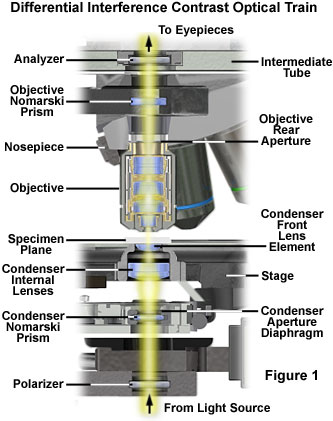
All of the major microscope manufacturers produce DIC accessories for their research-level microscopes, and these are often bundled together as matched kits containing all of the required hardware and optical components. In the standard configuration, a differential interference contrast microscope (see Figure 1) contains the polarizing elements typically encountered on a polarized light microscope and, in addition, two specially constructed birefringent compound prisms. Termed Wollaston or Nomarski prisms, these optical beamsplitters (and beam combiners) are positioned to project interference patterns of sheared wavefronts into the condenser front focal plane and the objective rear focal plane.
Presented in Figure 1 is the typical optical train configuration for a transmitted differential interference contrast microscope. Semi-coherent wavefronts emitted from localized neighborhoods in the lamp filament pass through a linear polarizer positioned between the light port in the microscope base and the condenser assembly. A compound Nomarski or Wollaston prism is located in or near the condenser aperture (front focal plane), and serves to align and shear incident polarized wavefronts into two orthogonal components. The perpendicular, sheared wavefronts are focused by the condenser lens system into parallel bundles that traverse the specimen plane and respond to refractive index and thickness gradients by deformation according to optical path length parameters of the specimen.
Light waves gathered by the objective converge at the rear focal plane where a second Nomarski prism is located. The objective Nomarski prism recombines sheared and deformed wavefronts into linear and elliptically polarized light that subsequently passes a component through the analyzer (a second polarizer oriented perpendicular to the substage polarizer) located in an intermediate tube above the objective. Finally, the linear polarized light components that emerge from the analyzer recombine through constructive and destructive interference at the image plane in the eyepiece diaphragm (or camera projection lens).
Polarizing Elements for DIC Microscopy
The polarizers employed in DIC microscopy are similar or identical to those used for polarized light observations, but many manufacturers offer matched DIC polarizing filters that have both low and high light transmission efficiencies. At the upper end of the magnification range (40x, 60x, and 100x), polarizers with high transmission efficiencies are preferred for DIC because specimen details are more clearly delineated and larger bias retardation values can be utilized for video and digital imaging. The low transmission polarizing filters are useful for DIC observation using the 10x and 20x objectives, but severely restrict light transmission at higher magnifications.
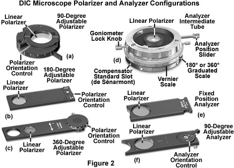
On most microscopes, the polarizer is mounted directly onto the light port in the base of the instrument or in a filter holder attached underneath the condenser. Polarizers designed to span the light port generally are mounted in a rotating assembly that enables the microscopist to rotate the filter through a 90 to 180-degree angle (see Figure 2(a)). Once the rotating polarizer is positioned at the desired transmission azimuth, it can be secured into place with a locking screw. By convention, the polarizer is oriented with the vibration transmission axis positioned in an East-West direction (left to right when standing in front of the microscope). Microscopes that have the polarizer attached to the substage condenser mounting bracket are provided with a housing that may or may not enable rotation of the polarizer (Figures 2(b) and 2(c)). Polarizers having circular geometry fit into a bracket in the stage and can rotate in fixed increments of 45 degrees with a dÚtente. Other polarizers are mounted in rectangular frames that slide into a slot in the condenser bracket (Figures 2(b) and 2(c)), and often contain thumbwheels that enable rotation through 180 to 360 degrees.
Analyzers are placed between the objective Nomarski prism and the eyepiece observation tubes in microscopes equipped for DIC observation, similar to the location of these components in polarized light microscopes. The analyzer is also a linear polarizer that is positioned with the transmission azimuth oriented at a 90-degree angle with respect to that of the polarizer. By convention, the vibration direction for the analyzer is North-South, which coincides with the East-West orientation prescribed for the polarizer.
The microscope mounting configuration for analyzers is equally as varied as it is for polarizers, and these components are commonly inserted into the optical train throughout a number of locations. In some microscopes, the analyzer is fixed into a rectangular frame (Figure 2(e)) and inserted into a slot in the nosepiece, intermediate tube, or vertical illuminator. Other analyzer designs feature the same frame style, but enable rotation of the analyzer element with a thumbwheel that is often graduated in 10, 45, or 90-degree increments (Figure 2(f)). Polarized light microscopes equipped for DIC observation often house the analyzer in an intermediate tube (see Figure 2(d)) located between the objective nosepiece and the observation tubes. These units are often designed for precision measurements in polarized light and feature 360-degree graduated vernier scales wrapped around the circumference, with a locking mechanism to secure the analyzer in the desired transmission azimuth. In addition, the analyzer is usually mounted on a slider so that it can be conveniently removed from the light path for linearly polarized or brightfield observation. Intermediate tubes for polarized light microscopy also contain a 20 x 6 millimeter DIN standard slot for a quarter-wavelength, full-wave, or de SÚnarmont compensator (Figure 2(d) and Figure 5).
Modern microscopes position the polarizer and analyzer in strategic locations with respect to the field lens, condenser, objective and observation tubes. In older microscopes, these polarizing elements can be found installed in a wide variety of locations. It should be noted, however, that placing polarizing elements in or very near a conjugate image plane (the field diaphragm, specimen stage, or eyepiece fixed aperture) is not a good idea, because scratches, imperfections, dirt, and debris on the glass surface can be imaged along with the specimen.
Condenser and Objective Prisms
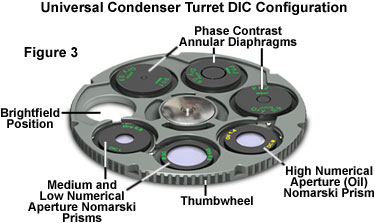
DIC condenser prisms, which act as beamsplitters to produce an angular shear to incoming polarized light wavefronts, are often mounted in a revolving turret condenser designed to house at least three individual prisms, as illustrated in Figure 3. Turret specifications and configurations vary according to the manufacturer, but they generally contain slots for four to eight auxiliary components, including Wollaston or Nomarski prisms, phase contrast annular rings, or darkfield light stops. The condenser turret illustrated in Figure 3 contains seven openings, three of which are filled with phase contrast annuli and three with DIC prisms. The open slot is used for brightfield observation.
Each condenser DIC prism (also termed compensators or auxiliary prisms) must be specifically matched to a narrow range of objective numerical apertures, so a particular prism may only work for one or two objectives (for example, the 10x and 20x). As a result, between three and five condenser prisms must be employed to match the entire objective magnification range between 10x and 100x. Some manufacturers tailor each condenser prism for a particular objective, thus requiring up to seven condenser prisms to span the entire spectrum of dry and oil immersion objectives having varied numerical apertures.
Condenser DIC prism inserts are constructed with anodized circular aluminum plates having the combination prism (usually circular in shape) secured in a precise orientation with optical cement. DIC prism wedges are very thin and cut with close tolerances to ensure that angular shear values match those required by the objective numerical aperture. The polished plates must be handled carefully to avoid contamination from fingerprints, oil, dirt, and debris. Each prism frame contains a slot or pin that mates to a corresponding partner in the condenser turret in order to define and secure alignment of the condenser prism with respect to the objective prism and the polarizer (and analyzer) axes.
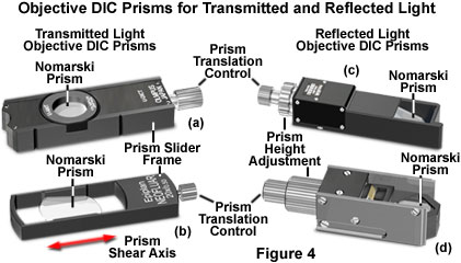
Positioned between the objective and the analyzer is a second Nomarski compound prism that acts to recombine wavefronts sheared by the condenser prism (Figures 1, 4, and 5). This prism, often termed the objective or principal DIC prism, can either be matched to a specific condenser prism, or a single objective prism can serve to recombine wavefronts having the spectrum of shear angles represented by all of the condenser prisms. A majority of the microscope manufacturers configure their DIC microscopes to employ a single objective Nomarski prism, which is mounted in a rectangular frame that slides into the nosepiece (see Figure 4). In order to introduce bias retardation into the DIC optical system, the objective prism rides on a gliding support that can be translated back and forth across the microscope optical axis by means of a micrometer control knob.
Objective DIC prisms designed to introduce bias retardation through translation across the microscope optical axis are fabricated in a rectangular shape with the long axis corresponding to direction of prism shear (Figure 4(b)). In a properly aligned DIC microscope, the condenser prism is imaged onto the objective prism by the combined action of the condenser and objective lens systems. As a result, the wavefront shear produced by the condenser prism is exactly matched at every point along the surface of both prisms (which are inverted with respect to one another). Translating either prism along the shear axis produces a wavefront mismatch (bias retardation), which, in turn, introduces an optical path difference that is uniform across the microscope aperture. Translating the objective prism with the micrometer control is the most popular mechanism for producing bias retardation in DIC microscopes.
Several objective prism slider designs from various manufacturers are illustrated in Figure 4. All of the compound prisms are housed in rectangular frames with a translational control knob positioned at the end of the frame. The control knob is employed to shift the prism position laterally along the shear axis (Figure 4(b)) in order to introduce bias retardation (or a net wavefront optical path difference), into the differential interference contrast optical train. Nomarski prism sliders designed for reflected light DIC microscopy also contain a second control knob (Figure 4(c) and 4(d)) that enables adjustment of the prism height to match varying rear focal plane positions throughout the entire objective magnification and numerical aperture range. When the microscope is operated in another imaging mode, the objective prism frame can be conveniently removed from the optical path by sliding the entire frame without removing it from the nosepiece or intermediate tube housing.
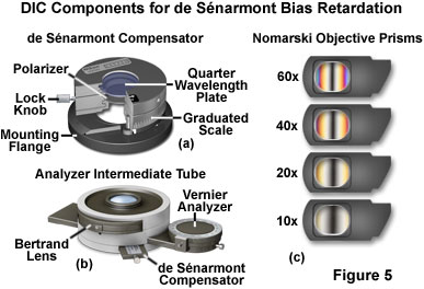
In DIC microscopes designed to introduce bias retardation using a de SÚnarmont compensator, the objective Nomarski prisms are secured with fixed mounts that slide into the nosepiece above the objectives (Figure 5(c)). Microscopes using de SÚnarmont compensators require a separate objective prism for each objective, but can often utilize the same condenser Nomarski prism for two or more objectives. The fixed objective prism mounts (Figure 5(c)) are easily removed from the light path by sliding the frame away from the microscope nosepiece.
A typical polarizer and quarter-wavelength retardation plate configuration for de SÚnarmont differential interference contrast is illustrated in Figure 5(a). This unit is fitted over the field diaphragm adjustment knob on the microscope base and, after alignment of the retardation plate optical axis and polarizer transmission azimuth, secured to the knob with a locking setscrew. The polarizer axis is marked on the front of the de SÚnarmont compensator unit, and graduated rulings enable the operator to qualitatively determine the approximate amount of bias retardation introduced into the system when the polarizer is rotated. The locking knob can be utilized to hold the polarizer immobile with respect to the quarter-wavelength plate. For brightfield observation or enhanced contrast techniques without DIC, the entire polarizer and retardation plate assembly can be removed from the optical path by swinging out the hinged upper section.
An alternative technique for de SÚnarmont DIC compensation is to place the quarter-wavelength compensator plate in the optical train between the objective Nomarski prism and the analyzer. In this case, either a standard linear polarizer is employed beneath the condenser prisms or the de SÚnarmont compensator illustrated in Figure 5(a) is set with the polarizer axis parallel to the retardation plate fast axis (only linear polarized light emerges from the compensator) and perpendicular to the analyzer. An intermediate tube designed for introducing de SÚnarmont DIC compensation after the objective prism is illustrated in Figure 5(b). In this case, bias retardation is introduced into the optical system by rotating the analyzer, rather than the polarizer.
Equipped with a Bertrand lens for observing the objective rear focal plane, the intermediate tube presented in Figure 5(b) also has a DIN standard slot able to accommodate a variety of retardation plates, including a de SÚnarmont compensator (shown in the Figure). The analyzer can be rotated by a precision graduated vernier mechanism, which enables the operator to quantitatively determine the level of bias retardation introduced into the DIC optical system. With de SÚnarmont compensators, bias retardation values ranging between one-twentieth and a full wavelength can be easily measured with an accuracy of 0.15 nanometers. In addition, the Bertrand lens can be conveniently inserted into the light pathway by means of a thumbwheel in order to observe events occurring at the objective rear focal plane. The use of a Bertrand lens or phase telescope to monitor the objective focal plane is critical to DIC microscope alignment, as discussed below.
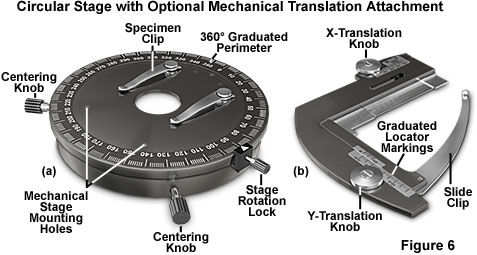
In DIC microscopy, contrast is a function of specimen orientation, and the wide variety of geometries encountered often requires repositioning of the specimen to maximize contrast effects for observation of the target structures. Use of standard rectangular mechanical stages to observe DIC specimen is hampered by the limited range of rotational motion exhibited by these components, although the x-y translation mechanism eases the burden of carefully examining the entire contents of a microscope slide. In order to allow specimens to be easily rotated and manipulated to present the optimum azimuthal contrast, a circular rotation stage similar to that illustrated in Figure 6(a) is recommended for DIC microscopy. The circular stage enables 360-degree rotation of the specimen, which is often necessary with extended linear specimens (such as diatoms or filamentous structures) that display extreme azimuthal contrast effects in DIC. Translation of the specimen during observation is aided by the utilization of a graduated mechanical stage accessory (Figure 6(b)) that attaches directly to the circular stage and securely clamps a microscope slide. The stage should be centered along the microscope optical axis, either by adjusting the position of the stage itself or by centering the objectives and condenser with respect to the stage.
Objectives designed for differential interference contrast must be free of strain or birefringent occlusions that depolarize light and lead to image degradation. In the past, microscopists were limited to strain-free achromat and fluorite objectives intended for observations in polarized light, but modern objectives having higher correction factors can now be employed for DIC microscopy. Termed universal objectives, these advanced lens systems can often be used for combined DIC, fluorescence, phase contrast, and brightfield microscopy without having to change objectives. In addition, newer apochromatic objectives have been designed that are sufficiently strain free to enable their use in polarized light and differential interference contrast observation, dramatically improving the image quality and resolution at higher magnifications.
Differential Interference Contrast Microscope Alignment
Before attempting to configure a microscope for observation in differential interference contrast, inspect the instrument to ascertain whether all of the necessary components are present, and free of lint, dust, and debris. Objective and condenser lens elements that contain stress signatures can degrade images in DIC, as can dirty lens surfaces, scratches, and contaminating foreign material in the optical pathway. Proper alignment of the microscope is essential to achieving optimum results and producing images that display pseudo three-dimensional and shadow-cast effects. Many of the steps outlined in the following procedure are only necessary when first aligning the microscope for DIC and do not require repetition for daily observations. Other steps should be taken each time the microscope is used for DIC investigations.
Preliminary Microscope Inspection - Examine the microscope carefully to ensure that all necessary DIC components are installed, or available and ready for use when necessary. Remove the condenser, disassemble the turret, and inspect the condition of the Nomarski or Wollaston prisms. The surfaces of these compound prisms should be clean and free of dust and debris. Because they are housed within the condenser turret, DIC condenser prisms rarely become contaminated with fingerprints, but dust and lint can easily flow into the turret and land on one of the flat quartz surfaces. To clean a contaminated prism surface, use a rubber balloon to remove loose fibers and dust, and/or gently wipe the surface with lens tissue or moist soft cotton. Be careful not to scratch the surfaces. The same treatment should be afforded to the objective prism(s), condenser and objective external lens elements, microscope eyepiece lenses, and the field lens at the field diaphragm port in the base of the microscope (or attached to the pillar of an inverted microscope). After ensuring the critical components are clean, reassemble the microscope, install the polarizer and analyzer, and then align the optical system for K÷hler illumination.
Install the Polarizer and Analyzer - With the microscope disassembled (condenser, DIC prisms, and at least one objective removed), install the polarizer and analyzer in their positions beneath the condenser and above the objective, respectively. In a manner similar to polarized light microscopy, the polarizer and analyzer are positioned so their transmission azimuths are crossed at a 90-degree angle (perpendicular) to one another. The polarizer, which is mounted between the light source and the condenser, is traditionally oriented in an East-West direction, or left to right when facing the microscope. In some cases, the positions of both the polarizer and analyzer are pre-determined by their fixed position in the mounting frames, and these components can only be inserted into the microscope optical pathway with a single orientation. Usually, a marker on the polarizer mount indicates the transmission direction, but some microscopes are equipped with a rotating polarizer mount that is graduated in degrees (Figure 2). The analyzer may also be rotatable with a graduated knob, and/or may contain a mark indicating the transmission axis.
When the polarizer and analyzer are crossed (transmission axes oriented at a 90-degree angle), the viewfield appears very dark when observed through the eyepieces. This condition is referred to as maximum extinction. If a significant amount of light passes through the microscope and the viewfield is not dark (or almost black), check to ensure the polarizer and analyzer are crossed. After crossing the polarizers, insert the condenser and objective, but do not install the objective Nomarski prism slider (or fixed mount). Rotate the condenser turret to the brightfield position (the slot lacking a phase plate or DIC prism). The viewfield should remain dark, but if either of these components (the condenser or objective) contains strained lens elements, some light may pass through. Remove one of the polarizing elements from the optical train (either the polarizer or analyzer) before proceeding to the next step.
Establish K÷hler Illumination - Before proceeding with DIC configuration (after the polarizers are installed), the microscope optical system should be aligned for brightfield specimen observation using the standard K÷hler technique. When properly configured, an image of the light source (usually a tungsten-halogen lamp) should be projected onto the condenser aperture diaphragm plane by the collector lens housed in the lamphouse or along the optical train inside the microscope frame base. Simultaneously, the condenser lens system also projects an image of the field diaphragm into the specimen conjugate plane (at the microscope stage). After the lamp filament has been centered (most modern lamphouses contain a pre-centered lamp), close the condenser aperture diaphragm and align the condenser with the microscope optical axis in brightfield illumination (the condenser turret is set to the 0 or B position). Bring the diaphragm into focus, superimposed on a focused specimen using the 10x objective, and open the iris leaves until only a small portion of the diaphragm is visible at the peripheral edges of the viewfield. Similar steps are taken for each objective being used, making sure the microscope is properly configured for K÷hler illumination for each objective in turn by adjusting both the field and aperture diaphragms. During the course of daily observations in DIC, the microscope should be periodically checked to ensure that K÷hler illumination is maintained.
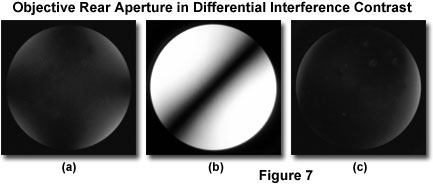
Inspect the Objective Rear Aperture - After configuring the microscope for K÷hler illumination, insert the polarizer and analyzer and examine the objective rear focal plane with a phase telescope or Bertrand lens (conoscopic observation mode). If the polarizer and analyzer are properly positioned and the microscope perfectly aligned, a dark extinction cross will appear in the objective aperture, as illustrated in Figure 7(a). The arms of the extinction cross should be oriented vertically and horizontally, with a small amount of light appearing at the four corners of the aperture (Figure 7(a)). Bright spots in the cross or highly birefringent regions, which affect the integrity of the extinction cross, are an indicator of strained optics. In addition, dust and lint particles positioned near a conjugate aperture focal plane (condenser or objective) will appear bright when viewed at the objective rear aperture. If birefringent spots are present, check another strain-free objective to determine whether the first objective or the condenser lens system is strained. Remove any contaminating dust from the objective or condenser lens surfaces and replace strained optical components (if possible) before proceeding to the next step.
Objective DIC Prism Alignment - Install the objective prism by either inserting the slider (Figure 4) or a prism confined to a fixed mount (for systems utilizing de SÚnarmont bias retardation; see Figure 5). Once the prism is in position, examine the objective rear focal plane once again with the phase telescope or Bertrand lens. The viewfield should now appear very bright, but featureless, with a single dark interference fringe extending across the diameter of the aperture at a 45-degree angle (see Figure 7(b)) along the shear axis. Depending upon whether the microscope is upright or inverted, the interference fringe will traverse the objective rear aperture in a northeast-southwest (upright) or northwest-southeast (inverted) direction. In either case, the interference fringe should be well defined, as illustrated in Figure 7(b), and positioned in the center of the aperture.
In some DIC microscope designs, the objective prism is fixed (de SÚnarmont compensation), while in others the prism can be translated back and forth across the optical axis by means of a positioning screw mechanism in the slider frame. In the latter case, slowly twist the adjustment knob while observing the objective rear focal plane through the telescope or Bertrand lens. As the knob is turned, the interference fringe should move away from its central position to either the upper or lower half of the bright rear aperture. Alternatively, turning the polarizer in a de SÚnarmont compensator will produce the same effect.
Condenser DIC Prism Alignment - Remove the objective prism from the optical train, and swing the lowest aperture condenser prism (for use with the 10x objective) into position by rotating the condenser turret. The appropriate position is usually marked by the red or white 10 setting on the turret (or a similar code, such as L). Refocus the phase telescope or Bertrand lens to observe the interference fringe that appears in the objective rear focal plane. Once again, a single fringe should be present having the same orientation as the fringe produced by the objective prism (northeast-southwest for upright microscopes or northwest-southeast for inverted microscopes). The interference fringes for the condenser and objective prisms should appear almost identical and should have the same orientation along the shear axis.
In order to clearly observe the condenser prism interference fringe using high-numerical aperture condensers designed for oil immersion, it may be necessary to remove the front lens assembly using the swing-lens control lever. If the fringe appearing in the objective aperture is not correctly positioned, it may be necessary to adjust the orientation or alignment of the condenser prism. In most cases, condenser prisms are assembled in a protective circular aluminum frame (Figure 3) with a notch or pin (or a lock-down screw) to ensure correct positioning within the condenser turret. Occasionally, a condenser prism can be forced into the turret without proper alignment, which will be apparent when the interference fringe is examined. If a condenser prism appears to be out of alignment, check with the microscope manufacturer for instructions on proper adjustment of the condenser DIC prisms.
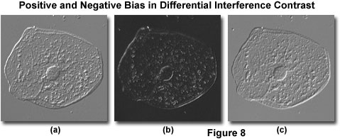
Specimen Observation - With the microscope aligned for K÷hler illumination, the polarizer and analyzer crossed, and both prisms (objective and condenser) installed, place a thin transparent mounted specimen (such as a buccal mucosa epithelial cell preparation) on the stage. Adjust the microscope for maximum extinction, and focus the specimen while observing the procedure through the eyepieces in orthoscopic mode (no Bertrand lens or phase telescope). The image observed in the viewfield should appear very dark gray, almost black, at maximum extinction with bright highlights in regions having sharply defined thickness or refractive index gradients (for example, the cellular membrane and nucleus; see Figure 8(b)). Spherical specimens with a high refractive index, such as immersion oil droplets, may even act as tiny lenses, and appear with a sharply defined interference fringe or band traversing the central region oriented in the same direction as the fringes are when observed in the objective rear aperture.
While observing the focused specimen image, translate the objective DIC prism using the slider knob or rotate the polarizer (or analyzer) in a microscope equipped for de SÚnarmont compensation. This action is termed introduction of bias retardation, and will translate the interference fringe bisecting the specimen along the shear axis and produce a corresponding change to specimen appearance. Shifting the prism in one direction (positive bias) will lighten specimen features at one edge while darkening the same features on the opposite edge and simultaneously lighten the background (see Figure 8(a)). In general, the specimen assumes a pseudo three-dimensional appearance with a shadow-cast effect oriented in the same direction as the shear axis. Moving the prism to the other side of the microscope optical axis (negative bias) will reverse the light and dark specimen regions (compare Figure 8(a) with Figure 8(c)).
At maximum extinction with all DIC components properly installed and aligned, the objective rear aperture appears dark gray (almost black) and relatively uniform when observed with a phase telescope or Bertrand lens (Figure 7(c)). In most cases, the central region of the rear aperture appears jet black while some evidence of light appears in the four quadrants at the periphery. The extinction cross should generally appear quite similar to that observed with crossed polarizers alone, but usually is much darker and covers a larger region of the objective rear aperture. The bright areas surrounding the periphery (Figure 7(c)) result from an artifact that arises through partial depolarization of light at the surface of the polarizers and lens elements in the condenser and objective.
Differential interference contrast images can be significantly improved by masking the bright regions at the periphery of the extinction cross in the objective rear aperture. This is accomplished by reducing the size of the condenser aperture diaphragm to eliminate the bright edges. In general, the objective rear aperture size should be reduced with the condenser diaphragm to approximately 75 or 80 percent of the full aperture. When the optical system is in perfect alignment, the extinction cross appears upright (see Figure 7) and can be observed to consist of two broad interference fringes, each shaped in a right angle and meeting at the center of the objective rear aperture (the fringes can also be visualized in orthoscopic mode in lower quality microscopes).
On some microscopes, the condenser and objective prism positions can be adjusted to yield a more uniform fringe pattern, resulting in the central region of the aperture appearing darker and more uniform. This task is accomplished to loosening and rotating (or raising or lowering) the condenser prism or by uncrossing the polarizer and analyzer by a couple of degrees. Occasionally microscopes contain setscrews that allow for adjustment of the condenser and objective prisms, but models so equipped are becoming rare. As a final check on microscope alignment, adjust the condenser focus knob while examining the extinction pattern in the objective rear aperture to determine whether it can be improved. Note that a significant repositioning of the condenser may degrade optical performance by separating the overlap between conjugate interference planes of the objective and condenser DIC prisms.
Adjusting the bias retardation by translating the objective prism, or rotating the polarizer in a de SÚnarmont configuration, dramatically improves the image appearance (over that observed at maximum extinction) and increases contrast. This maneuver is essential for imaging specimens in differential interference contrast, and represents the last step in the adjustment of the microscope optical train. In many cases, a gradient of light appears across the entire field of view when observing DIC images. This occurs in addition to the presence of light and dark intensities at opposite edges of the specimen, and is due to a broad and indistinct field fringe artifact produced by the optical system. Microscopes having well-matched optical components maximize the size of the field fringe, which can become so broad and evenly distributed that the entire field appears a uniform medium gray color. In most cases, however, some evidence of the fringe remains, and the viewfield exhibits a shallow gradient of light intensity (medium to light or darker shades of gray) from one peripheral edge to the other. This artifact is inherent in a particular optical configuration and should be ignored when observing and collecting images of DIC specimens.
Compensators in DIC Microscopy
Specimen contrast can also be increased by introducing a retardation plate (or compensator) into the optical pathway in a DIC microscope. In general, a full-wave (also termed a first-order compensator) plate is inserted in an intermediate tube between the objective prism and the analyzer, although the plate can also be situated after the polarizer but before the condenser prism. These plates exhibit a retardation level of an entire wavelength at a specified value in the green region (usually near 550 nanometers), and result in the specimen displaying yellow and blue Newtonian interference colors along refractive index and thickness gradients. The background is rendered magenta due to the subtraction of green wavelengths from white light.
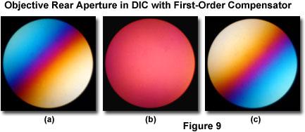
In a de SÚnarmont or a standard (translatable) Nomarski prism DIC microscope configuration, when the objective prism is positioned with the extinction interference fringe in the center of the optical pathway, a pattern similar to that displayed in Figure 7(b) is observed at the objective rear focal plane (provided the condenser prism is removed from the optical path). If a full-wave retardation plate is then placed between the objective prism and the analyzer, the interference pattern illustrated in Figure 9(a), which displays a spectrum of Newtonian interference colors, appears in the objective rear focal plane. Removing the objective prism from the light path and inserting a condenser prism yields the pattern presented in Figure 9(c). When both the objective and condenser prisms are present in the optical train and adjusted to the extinction position, a magenta color is visible in the objective rear focal plane (Figure 9(b)).
Translating the objective Nomarski prism or rotating the polarizer in a de SÚnarmont compensator configuration will shift the Newtonian interference pattern color illustrated in Figure 9(b). Introducing negative bias will shift the Newtonian colors to subtractive values (yellow), while shifting the prism to positive bias values will result in additive colors (blue). The colors produced by specimen gradients can be compared to a Michel-Levy reference chart in order to determine the magnitude of optical path differences.
DIC Microscope Configurational Errors
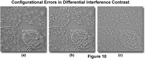
When a differential interference microscope is properly configured, the resulting images display a realism manifested in pseudo three-dimensionality through a shadow-cast effect that appears to originate from a highly oblique angle (see Figure 10(a)). However, even slight alignment errors can result in a deterioration of minute specimen detail, and serious mistakes in configuration can yield a dramatic loss of contrast that renders the image useless. The most common errors in DIC microscope configuration result from polarizers that are not crossed, a mismatch between the objective and condenser prisms, a missing condenser DIC prism, or incorrect setting of the condenser iris aperture. Other problems can arise, especially if the condenser and/or objectives are not strain free, but these mistakes are rare if the microscope is designed specifically for imaging specimens in DIC illumination.
Ensuring that the polarizers are crossed and positioned in the correct orientation was discussed previously in the section on microscope alignment. Occasionally, either the polarizer or analyzer can become accidentally rotated out of position by brushing against the thumbwheel or careless use of the instrument. As a result, overall specimen contrast is reduced, but many features often remain visible. This type of mistake can be eliminated by utilization of a fixed polarizer and analyzer or by ensuring that the locking knob is set to suspend polarizer rotation. Most polarizers housed in rotating mounts contain marks that indicate the position of the transmission azimuth. A careful check of the polarizer and analyzer orientation prior to commencing DIC observations will avoid errors with these components.
Accidental mismatch between the objective and condenser prisms is another common source of errors in differential interference contrast microscopy. Because of the shear angle discrepancies between prisms not designed to work together, the resulting image exhibits extremely poor contrast (see Figure 10(c), which cannot be corrected by translating the objective prism or rotating the polarizer in a de SÚnarmont compensation microscope. The condenser turret is usually marked with a code that identifies the prism placed into the optical pathway. Inspection of the exterior code order to ensure that condenser prisms are positioned in the correct slot will help to avoid this type of error. Also, the prism code inscribed on the objective barrel should match the code for the condenser prism in use. In general, prism mismatches occur when the magnification is changed, but the condenser turret is not rotated to insert a matching prism into the optical pathway. Occasionally, a condenser prism may be missing from the condenser or the condenser turret rotated into a position that does contain a prism (for example, the brightfield position; see Figure 3). The result is an image similar to that illustrated in Figure 10(c), which lacks contrast and does not display the high resolution obtainable with differential interference contrast.
The condenser iris diaphragm is typically employed to adjust depth of field and contrast for images observed in the eyepieces or recorded digitally and on film. In differential interference contrast microscopy, wide aperture sizes are useful for optical sectioning experiments, where a shallow depth of field is required, but high resolution is also necessary. Often, the compromise between maximum contrast afforded by using smaller apertures is offset by the elimination of interfering specimen features located away from the plane of focus. If the condenser aperture is not opened sufficiently (to about three-quarters to four-fifths of the objective aperture), diffraction artifacts can obscure important specimen detail and seriously degrade image appearance (Figure 10(b)). In general, diffraction effects can be avoided by maintaining the condenser iris diaphragm size between 80 to 90 percent of the objective aperture.
Additional errors can occur due to spherical aberration when using thick specimens immersed in water, or when the glass microscope slide, culture dish, or coverslip is too thick. These mistakes are manifested by images that are not sharply focused and lack the shadowed relief that is characteristic of DIC images. Correction collars on high magnification dry objectives can often be adjusted to correct for spherical aberration, but specimens that are too thick must be replaced with thinner sections. When examining cells in culture, do not use DIC optical systems with culture vessels made from injection-molded polymers. These materials display stress birefringence and will produce confusing images. Instead, use glass vessels designed especially for DIC microscopy, which are available from several manufacturers. In general, careful attention should be paid to selection of high-quality glass microscope slides and coverslips manufactured to precise tolerances, and the glass should be thoroughly cleaned and dried prior to preparation of specimens.
Illumination Sources for DIC Microscopy
At lower magnifications (10x through 40x), a 50-watt quartz halogen lamp can provide enough light for satisfactory observation and recording of images in DIC. However, at the highest magnifications (60x and 100x), at least a 100-watt tungsten-halogen light source is recommended. The illumination intensity required by the light source is dependent upon the transmission percentage of the polarizer and analyzer, and many older DIC microscopes are equipped with polarizing elements that have low transmission values (20 percent or less). However, later model microscopes are often equipped with high transmission polarizers (greater than 30 percent), which enable a higher flux density to pass through the optical system, providing adequate light for observation and imaging at the highest magnifications.
Although coarse structural detail, such as the edges of cells and larger intracellular components (nuclei) can be easily visualized with a high-intensity tungsten-halide lamp, in order to observe the finest structural details, very intense illumination having a narrow bandwidth is essential. Mercury arc-discharge lamps feature a high-energy peak in the central portion of the visible spectrum at 546 nanometers (green), which can be further refined by passage through a narrow bandwidth (10 nanometer) interference filter centered at 546 nanometers. In addition, a light scrambler can be employed to enhance the narrow bandwidth illumination to achieve the highest possible resolution. Note that the objective aperture should be fully illuminated, regardless of the light source, for the best results.
Conclusions
The correct placement and orientation of optical components in a differential interference contrast microscope is critical to optimum performance, regardless of the target magnification and resolution. Improper adjustment of even a single component can result in serious image degradation and upset the shadow-cast effect and resolution of the instrument. The two compound prisms and their associated polarizers in DIC microscopy are mirror image pairs. Light waves passing through the initial polarizer and condenser prism are imaged onto the objective prism and analyzer to produce the final image. All four of these components must be in the proper orientation in order for DIC to function properly. Contrast is generated either by altering the lateral position of the objective prism, or by rotating the polarizer in de SÚnarmont compensation instruments. In this manner, the optical path difference between wavefronts is increased or decreased to produce contrast in the specimen.
It should be noted that contrast in DIC is a function of gradients in the specimen optical path length, which are rendered in pseudo three-dimensional relief when the microscope is properly adjusted. Because contrast arises from a combination of refractive index fluctuations and/or thickness variations, apparent gradients observed with the technique can correspond to real changes in specimen topography or may be a function, for example, of localized protein concentration gradients. Only independent knowledge of the structural properties relating to the specimen can help determine the absolute nature of contrast effects in DIC microscopy.
In addition, even when it is determined that shadow-cast effects can truly be ascribed to height changes in the specimen, there is no inherent mechanism in DIC to indicate which features represent plateaus or valleys at a particular setting of the objective prism. A qualitative solution to the problem is to locate a known specimen characteristic, such as a scratch in the glass, and observe how the feature responds to bias retardation as the objective prism is translated across the optical axis. Integral specimen features having a similar response will be either valleys or plateaus, while those with opposite responses will have a reverse orientation.
When examining unknown specimens with differential interference contrast, the microscopist should be alert to interference colors arising at the edges, which are normally featureless and exhibit either a very light or dark color, depending upon orientation. The presence of interference colors indicates that the specimen may be birefringent and, consequently, not a good candidate for DIC observation. This fact can be confirmed by examining the specimen under crossed polarized illumination with both the objective and condenser DIC prisms removed from the optical pathway.
Among the limitations imposed on differential interference contrast microscopy are the expensive birefringent Nomarski or Wollaston prisms necessary to perform the technique. These components are far more expensive than those required for phase contrast or Hoffman modulation contrast microscopy, which may serve as alternative techniques, especially when observing living cells in plastic vessels. In addition, very thin or scattered specimens often produce better images having more contrast when phase contrast is used instead of DIC. Older apochromatic objectives may not be suitable for DIC observation because the objectives themselves can significantly affect polarized light. The microscopist should check with the manufacturer before purchasing high-quality apochromatic objectives in conjunction with DIC optical components.
Contributing Authors
Douglas B. Murphy - Department of Cell Biology and Anatomy and Microscope Facility, Johns Hopkins University School of Medicine, 725 N. Wolfe Street, 107 WBSB, Baltimore, Maryland 21205.
Jan Hinsch - Leica Microsystems, Inc., 110 Commerce Drive, Allendale, New Jersey, 07401.
Edward D. Salmon - Department of Cell Biology, The University of North Carolina, Chapel Hill, North Carolina 27599.
Mortimer Abramowitz - Olympus America, Inc., Two Corporate Center Drive., Melville, New York, 11747.
Michael W. Davidson - National High Magnetic Field Laboratory, 1800 East Paul Dirac Dr., The Florida State University, Tallahassee, Florida, 32310.
BACK TO DIFFERENTIAL INTERFERENCE CONTRAST MICROSCOPY
