
Refraction of Light
When electromagnetic radiation, in the form of visible light, travels from one substance or medium into another, the light waves may undergo a phenomenon known as refraction, which is manifested by a bending or change in direction of the light. Refraction occurs as light passes from one medium to another only when there is a difference in the index of refraction between the two materials. The effects of refraction are responsible for a variety of familiar phenomena, such as the apparent bending of an object that is partially submerged in water and the mirages observed on a hot, sandy desert. The refraction of visible light is also an important characteristic of lenses that enables them to focus a beam of light onto a single point.

Early nineteenth century lacemakers relied on water-filled glass spheres to focus or condense candlelight onto small areas of their work in order to help them see fine details more clearly. Figure 1 illustrates a lacemaker's condenser made in the 1800s, which consists of several glass spheres arranged in a circle around a candle stand, enabling light from the candle to be focused or concentrated into several bright spots. The curved surface of the glass sphere functions as a large collecting surface for the light rays, which are then refracted toward a common focal point in a manner similar to that of a convex lens. Condensing or collecting lenses are also utilized in modern microscopes and other optical instruments to concentrate light, relying on the same principles of refraction as did the early lacemaker's condenser.
As light passes from one substance into another, it will travel straight through with no change of direction when crossing the boundary between the two substances head-on (perpendicular, or a 90-degree angle of incidence). However, if the light impacts the boundary at any other angle it will be bent or refracted, with the degree of refraction increasing as the beam is progressively inclined at a greater angle with respect to the boundary. As an example, a beam of light striking water vertically will not be refracted, but if the beam enters the water at a slight angle it will be refracted to a very small degree. If the angle of the beam is increased even farther, the light will refract with increasing proportion to the entry angle. Early scientists realized that the ratio between the angle at which light crosses the media interface and the angle produced after refraction is a very precise characteristic of the material producing the refraction effect.
| Interactive Java Tutorial | |||||||||||
|
|||||||||||
For centuries, man had noticed a rather odd, but obvious fact. When a straight pole or stick is partially submerged in water, the pole no longer appears straight, but slants off at a different angle or direction (see Figure 2 for an illustration of this effect with a soda straw in a glass of water). Light is refracted when it leaves water, giving rise to the illusion that objects in water appear to be both distorted and closer than they really are. The straw in Figure 2 appears magnified and slightly distorted due to refraction of reflected light waves from the surface of the straw. The waves must first pass through the water, then through the glass/water boundary and finally through the air. Light waves coming from the sides (front and back) of the straw are shifted to a greater degree than those coming from the center of the straw, making it appear larger than it really is.
As early as the first century (A.D.), the ancient Greek astronomer and geographer Ptolemy attempted to mathematically explain the amount of bending (or refraction) that occurred, but his proposed law was later determined to be unreliable. During the 1600s, the Dutch mathematician Willebrord Snell succeeded in developing a law that defined a value related to the ratio of the incident and refracted angles, which has subsequently been termed the bending power or refractive index of a substance. In effect, the more a substance is able to bend or refract light, the larger its refractive index value is said to be. The stick in water appears to be bent because light rays reflected from the stick are abruptly bent at the air-water interface before reaching our eyes. To his disappointment, Snell never discovered the reason for this refraction effect.

In 1678, another Dutch scientist, Christiaan Huygens devised a mathematical relationship to explain Snell's observations and proposed that the refractive index of a material is related to the speed at which light travels through the substance. Huygens determined that the ratio relating the angles of light paths in two materials having differing refractive indices should be equal to the ratio of the velocity that light travels when passing through each material. Thus, he postulated, light would travel more slowly through materials having a greater refractive index. Stated another way, the velocity of light through a material is inversely proportional to its refractive index. Although this point has since been verified experimentally, it was not immediately obvious to a majority of seventeenth and eighteenth century investigators who lacked a reliable means to measure the velocity of light. To these scientists, light appeared to travel at the same speed, regardless of the material through which it passed. It was over 150 years after Huygens passed away that the speed of light was measured with enough accuracy to prove his theories correct.
Expanding on the previous ideas, the refractive index of a transparent substance or material is defined as the relative speed at which light moves through the material with respect to its speed in a vacuum. By convention, the refractive index of a vacuum is defined as having a value of 1.0, which serves as a universally accepted reference point. The index of refraction of other transparent materials, commonly identified by the variable n, is defined through the equation:
where c is the speed of light in a vacuum, and v is the velocity of light in the material. Because the refractive index of a vacuum is defined as 1.0, and light attains its maximum speed in a vacuum (which is devoid of any material), the refractive index of all other transparent materials exceeds the value of 1.0, and can be measured by a number of techniques. For most practical purposes, the refractive index of air (1.0003) is so close to that of a vacuum that it can be employed to calculate refractive indices of unknown materials. The measured refractive indices of several common transparent materials are presented in Table 1. Materials with higher refractive indices slow the speed of light to a greater degree than those with lower refractive indices. In effect, these materials are said to be more refractive, and they exhibit a larger angle of refraction for incoming light rays passing through an air interface.
Refractive Index Values for Selected Media
|
||||||||||||||||||||||
Table 1
When a light wave passes from a less refractive medium (such as air) to a more refractive medium (such as water), the velocity of the wave decreases. Conversely, when light passes from a more refractive medium (water) to a less refractive medium (air), the velocity of the wave increases. The normal is defined as a line perpendicular to the boundary, or interface, between two substances. The angle of incidence in the first medium, with respect to the normal, and the angle of refraction in the second medium (also with respect to the normal), will differ in proportion to the difference in indices of refraction between the two substances. If a light wave passes from a medium of lower refractive index to one of higher refractive index, it is bent toward the normal. However, if the wave travels from a medium of higher refractive index to a medium of lower refractive index, it is bent away from the normal. Snell's Law describes the relationship between the angles of the two light waves and the indices of refraction of the two materials as:
In Snell's equation, the variable n(1) represents the refractive index of the medium in which the incident ray travels, while n(2) is the refractive index of the medium through which the refracted ray travels. The value q(1) represents the angle (with respect to the normal) at which the incident ray strikes the boundary, and q(2) is the angle at which the refracted ray travels.
There are several important points that can be drawn from the Snell equation. When n(1) is less than n(2), the angle of refraction is always smaller than the angle of incidence (bending toward the normal). Alternatively when n(2) is less than n(1), the angle of refraction is always greater than the angle of incidence (bending away from the normal). When the two refractive indices are equal (n(1) = n(2)), then the two angles must also be equal, enabling the light to pass through without refraction.
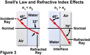
Figure 3 illustrates the two cases just described for n(1) greater than n(2) and n(1) less than n(2) for an arbitrary incidence angle of 45 degrees. The media consist of air and water with refractive indices of 1.000 and 1.333, respectively. On the left-hand side of Figure 3, a light wave passing through air is incident upon an aqueous surface at a 45-degree angle, and is refracted upon entering the water at a 32-degree angle from the normal. When the situation is reversed, a light ray having the same incident angle in water is refracted at a 70-degree angle when passing into air.
Rearranged to in a different form, Snell's Law demonstrates that the ratio of the sines of the incident and refracted angles is equal to a constant, n, which is the ratio of the light velocities (or indices of refraction) in the two media. This ratio, n(2)/n(1), is termed the relative index of refraction for those two substances.
Another aspect of the refractive index concept is illustrated below (Figure 4) for the case of a light beam passing from air through both glass and water and reemerging into air. Notice that while both beams enter the more refractive material through the same angle of incidence with respect to the normal (60 degrees), the refraction for glass is approximately 6 degrees greater than that for water due to the higher refractive index of glass.
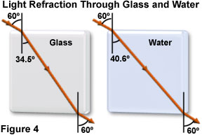
The beams are refracted upon entry, and again upon exiting the higher index materials, refracting in a direction that is reversed from the entry path. Both light beams exit at the same angle they had on entry, but the point of exit is shifted laterally along the boundary due to the different angular path taken by the beams while traversing each of the two higher index materials. This effect of refraction is very important in lens design for controlling the precise focal point of imaging light rays.
Refraction of light is an important aspect in the physics of lenses, especially with regards to how a single lens or multi-lens system is designed and constructed. In a simple convex lens, light waves reflected from the object are collected by the lens and refracted towards the optical axis to converge on the rear focal point (Figure 5). The relative position of the object with respect to the front focal point of the lens determines how the object is imaged. If the object is positioned beyond twice the distance of the focal point from the lens, then it appears smaller and inverted and must be imaged by an additional lens in order to magnify the size. However, when the object is closer to the lens than the front focal point, the image appears upright and larger, as can be easily demonstrated with a simple magnifying glass.

A number of phenomena that result from light refraction are often observed in everyday life. One of the most common is experienced by nearly everyone who has tried to reach for and touch something submerged in water. An object seen in the water will usually appear to be at a different depth than it actually is, due to the refraction of light rays as they travel from the water into the air. The eyes and brain trace the light rays back into the water as though they had not refracted, but traveled from the object in a straight line, creating a virtual image of the object that appears at a shallower depth.
| Interactive Java Tutorial | |||||||||||
|
|||||||||||
This concept is nicely illustrated by the illusion, created by refraction effects, of the actual depth of a fish in shallow water when observed from the bank of a lake or pond (see Figure 6). When we peer through the water to observe fish swimming around the pond, they appear to be much closer to the surface than they really are. On the other hand, from the fish's point of view, the world appears distorted and compressed above the water due to virtual images created by refraction of reflected and transmitted light reaching the eyes of the fish. In fact, due to refraction, a fisherman on the bank appears to be farther away from the fish (from the fish's viewpoint) than he or she really is.

This phenomenon can be used to determine the refractive index of a liquid with an optical microscope. A flat cell capable of holding liquid with a mark (or graduations) placed on the inside glass surface is constructed (or purchased) for this experiment. One of the microscope eyepieces must have a graduated reticle inserted at the primary image plane for line width measurements of the mark in the flat cell. Before adding the liquid of unknown refractive index to the cell, the microscope is focused on the mark at the bottom of the cell and a measurement of the mark's position on the reticle is noted. Next, a small amount of liquid is added to the cell and the microscope is refocused on the mark (through the liquid) and a new measurement is taken. The microscope is finally focused on the surface of the liquid, and a third reading is recorded by measuring the position of the mark on the reticle. The refractive index of the unknown liquid can then be calculated using the following equation:
where D(measured) is the measured depth (from the surface of the liquid to the position of the mark on the empty cell) using the microscope, and D(apparent) is the mark measurement with and without liquid.
Although it is generally true that light must pass from one substance into another to undergo refraction, there are circumstances in which perturbations, such as temperature gradients, can produce enough fluctuation in refractive index within a single medium to generate a refractive effect. If they have significantly different temperatures, overlapping layers of air in the atmosphere are responsible for producing what are often termed mirages, a phenomenon in which the virtual image of an object is observed to be positioned either above or below the actual object.
Layering of warmer and cooler air is especially common over desert areas, the ocean, and hot asphalt pavement such as parking lots and highways. The actual mirage effect that is visualized depends upon whether cooler air overlies warmer air, or vice versa (Figure 7(a)). One type of mirage appears as an upside-down virtual image directly beneath the real object, and occurs when a layer of warm air near the ground or water surface is trapped by denser, cooler air lying above. Light from the object traveling downward into the warmer air adjacent to the ground (or water) is refracted upward toward the horizon. At some point the light reaches a critical angle for the warm air, and is bent upward by total internal reflection, resulting in the virtual image appearing below the object.

Another form of mirage, termed looming, occurs when warm air lies over a layer of cooler air, and is common over large bodies of water that may remain relatively cool when the air above the water is heated during the day (see Figure 7(b)). Light rays from an object, such as a ship on the water, traveling upward through the cool air into the warmer air are refracted downward toward an observer's line of sight. The rays then appear to originate from above the object and it appears to "loom" above its actual position. It is common for ships at sea near the horizon to appear to float above the water.
Visible Light Wavelength Dispersion
Although reference is usually made to a standard and fixed refractive index for a substance, careful measurements indicate that the index of refraction for a particular material varies with the frequency (and wavelength) of radiation, or the color of visible light. In other words, a substance has many refractive indices that may differ either marginally, or to a significant degree, as the color or wavelength of light is changed. This variation occurs for nearly all transparent media and has been termed dispersion. The degree of dispersion exhibited by a specific material is dependent upon how much the refractive index changes with wavelength. For any substance, as the wavelength of light increases, the refractive index (or the bending of light) decreases. In other words, blue light, which comprises the shortest wavelength region in visible light, is refracted at significantly greater angles than is red light, which has the longest wavelengths. It is the dispersion of light by ordinary glass that is responsible for the familiar splitting of light into its component colors by a prism.
| Interactive Java Tutorial | |||||||||||
|
|||||||||||
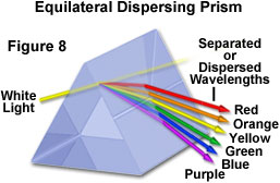
In the late seventeenth century, Sir Isaac Newton performed a series of experiments that led to his discovery of the visible light spectrum, and demonstrated that white light is composed of an ordered array of colors starting with blue at one end and progressing through green, yellow, and orange, finally ending with red at the other end. Working in a darkened room, Newton placed a glass prism in front of a narrow beam of sunlight emerging through a hole drilled into a window shutter. When the sunlight passed through the prism, an ordered spectrum of color was projected onto a screen placed behind the prism.
From this experiment, Newton concluded that white light is produced from a mixture of many colors, and that the prism spread or "dispersed" white light by refracting each color at a different angle so they could be easily separated (Figure 8). Newton was unable to further subdivide the individual colors, which he attempted by passing a single color of dispersed light through a second prism. However, when he placed a second prism very close to the first, so that all of the dispersed colors entered the second prism, Newton found that the colors were recombined to produce white light again. This finding produced conclusive evidence that white light is composed of a spectrum of colors that can easily be separated and reunited.
The phenomenon of dispersion plays a critical role in a wide variety of common observations. Rainbows result when sunlight is refracted by raindrops falling through the atmosphere, producing a spectacular display of spectral color that closely mimics that demonstrated with a prism. In addition, the sparkling colors produced by exquisitely cut gems, such as a diamond, result from white light that is refracted and dispersed by precisely angled facets.
When measuring the refractive index of a transparent substance, the particular wavelength used in the measurement must be identified. This is because dispersion is a wavelength-dependent phenomenon, and the measured refractive index will depend on the wavelength of light used for the determination. Table 2 categorizes the dispersion of visible light in various media as shown by the variation of refractive index for three different wavelengths (or colors) of light.
Dispersion Values of Visible Light
|
||||||||||||||||||||||||||
Table 2
The most commonly used wavelength to measure refractive index values is emitted by a sodium lamp, which features a strong and closely spaced doublet having an average wavelength of 589.3 nanometers. This light is termed the D line spectrum, and represents the yellow light listed in Table 2. Likewise, F line and C line spectra correspond to blue and red light of specific wavelengths (also presented in Table 2) emitted by hydrogen. From the values given in the table, it is apparent that increasing the wavelength of light from 486.1 nanometers (blue or F line) to 656.3 nanometers (red or C line) produces an apparent decrease in refractive index for a particular medium. Dispersion can be quantitatively defined, using the three specific wavelengths for yellow, blue, and red light, as:
where n is the refractive index of the material at a particular wavelength designated by D, F, and C, which represent the spectral lines of sodium and hydrogen as discussed above (see Table 2). Many factors play a key role in the dispersion values of various materials, including the elemental and molecular composition, and the crystalline lattice morphology. Several inorganic solids have unusually high dispersions, including the chromates, dichromates, cyanides, vanadates, and halide complexes. Organic substituents can also contribute to high dispersion values when incorporated into certain materials.
Dispersion is also responsible for chromatic aberration, a lens artifact resulting from refractive index variation with wavelength. When white light is passed through a simple convex lens, several focal points arise in close proximity, which correspond to the minor refractive index differences of the component wavelengths. This effect tends to produce colored (either red or blue, depending upon focus) halos surrounding the images of objects. Correction of this aberration is accomplished by the use of combinations of two or more lens elements composed of materials having different dispersive properties. A good example is an achromatic doublet lens system constructed of two individual elements using both crown and flint glasses.
Critical Angle of Reflection
An important concept in optical microscopy is the critical angle of reflection, which is a necessary factor to consider when choosing whether to use dry or oil immersion objectives to view a specimen at high magnification. Upon passing through a medium of higher refractive index into a medium of lower refractive index, the path taken by light waves is determined by the incident angle with respect to the boundary between the two media. If the incident angle increases past a specific value (dependent upon the refractive index of the two media), it reaches a point at which the angle is so large that no light is refracted into the medium of lower refractive index, as illustrated in Figure 9. In this figure, individual light rays are represented by either red or yellow colored arrows moving from a medium of higher refractive index (n(2)) to one of lower refractive index (n(1)). The angle of incidence for each individual light ray is denoted by the value, i, and the angle of refraction by the variable, r. The four yellow light rays all have an angle of incidence (i) low enough to allow them to pass through the interface between the two media. However, the two red light rays have incident angles that exceed the critical angle of reflection (approximately 41 degrees for the water and air examples) and are reflected either into the boundary between the media or back into the higher refractive index medium.

The critical angle phenomenon takes place when the angle of refraction (angle r in Figure 9) becomes equal to 90 degrees and Snell's law reduces to:
where (q) is now termed the critical angle (denoted by the variable c). If the medium having a lesser refractive index is air (n = 1.00), the equation reduces to:
When the critical angle is exceeded for a particular light wave, it exhibits total internal reflection back into the medium. Usually the higher index medium is considered the internal medium, because air (having a refractive index of 1.0) is in most cases the surrounding, or external medium. This concept is especially critical in optical microscopy when attempting to image specimens with a medium other than air between the cover glass and the objective front lens. The most common immersion medium (other than air) is specialized oil having a refractive index equal to that of the glass used for the objective front lens element and the coverslip.
Optical devices ranging from microscopes and telescopes to cameras, charge-coupled devices (CCDs), video projectors, and even the human eye, rely in a fundamental way on the fact that light can be focused, refracted, and reflected. The refraction of light produces a wide variety of phenomena, including mirages, rainbows, and curious optical illusions such as making fish appear to be swimming in more shallow water than they really are. Refraction also causes a thick-walled beer mug to appear fuller than it really is, and deceives us into thinking the sun is setting several minutes later than it really does. Millions of people use the power of refraction to correct faulty vision with eyeglasses and contact lenses, which enable them to see the world more clearly. By understanding these properties of light, and how to control them, we are able to view details that are invisible to the unaided human eye, regardless of whether they are located on a microscope slide or in a distant galaxy.
Contributing Authors
Thomas J. Fellers and Michael W. Davidson - National High Magnetic Field Laboratory, 1800 East Paul Dirac Dr., The Florida State University, Tallahassee, Florida, 32310.