
Basic Aspects of Light Filters
A majority of the common natural and artificial light sources emit a broad range of wavelengths that cover the entire visible light spectrum, with some extending into the ultraviolet and infrared regions as well. For simple lighting applications, such as interior room lights, flashlights, spot and automobile headlights, and a host of other consumer, business, and technical applications, the wide wavelength spectrum is acceptable and quite useful.
However, in many cases it is desirable to narrow the wavelength range of light for specific applications that require a selected region of color or frequency. This task can be easily accomplished through the use of specialized filters that transmit some wavelengths and selectively absorb, reflect, refract, or diffract unwanted wavelengths. Filters are constructed in a wide variety of shapes and physical dimensions, and can be employed to remove or pass wavelength bands ranging in size from hundreds of nanometers down to a single wavelength. In other words, the amount of light excluded or limited by filters can be as narrow as a small band of wavelengths or as wide as the entire visible spectrum.
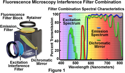
Many filters work by absorbing light, while others reflect unwanted light, but pass a selected region of wavelengths. The color temperature of light can be fine-tuned with filters to produce a spectrum of light having the characteristics of bright daylight, the evening sky, indoor tungsten illumination, or some variation in between. Filters are useful for adjusting the contrast of colored regions as they are represented in black and white photography or to add special effects in color photography. Specialized dichroic filters can be used to polarize light, while heat-absorbing filters can limit infrared wavelengths (and heat), allowing only visible light to pass through. Harmful ultraviolet rays can be exclusively removed from visible light by filters, or the intensity of all wavelengths (ultraviolet, visible, and infrared) can be reduced to specific ranges by neutral density filters. The most sophisticated filters operate by the principles of interference and can be adjusted to pass narrow bands (or even a single wavelength; see Figure 1) of light while reflecting all others in a specific direction.
Absorption Filters
Until the early twentieth century, liquid filters and large blocks of dyed glass were the primary means of filtering light. Many aromatic organic chemicals produce brilliantly colored solutions when dissolved in alcohol or water, and these provided a wide range of absorption filters for early photographers and scientists. In 1856, English chemist William Perkin accidentally discovered a natural substance, termed aniline purple or mauveine, while attempting to synthesize the drug quinine from coal tar. He found that the chemical produced beautiful deep purple-colored solutions when dissolved in alcohol and realized its tremendous potential for making dye products. Perkin's efforts led to a host of synthetic dyes, which gave birth to an industry that is responsible for producing practically all of the dyes currently in use.
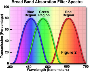
Today, absorption filters are made primarily from colored filter glass or synthetic gels, and represent the largest class and most widely used type of filters for applications that do not require a precise definition of transmitted wavelengths. Commonly utilized to isolate a broad band of wavelengths (see Figure 2), absorption filters are also helpful to block short wavelengths while transmitting longer ones. These filters are commonly available in the form of glass, plastic-coated glass, acetate, or gelatin bases that have been coated, mixed, or impregnated with organic and inorganic dyes obtained from both natural and synthetic sources. Among the materials used in glass and polymer filters are the rare earth transition elements, colloidal dyes (such as selenide), and other molecules having high extinction coefficients that produce reasonably sharp absorption transitions.
The quality of glass or polymer used in the manufacture of filters is important, and should be of optical grade and provide uniformity of density and color over the entire surface of the filter. Filter glass or plastic attenuates light only through absorption, so the spectral performance is dependent upon the thickness and optical density of the filter material. Increasing the thickness will produce a corresponding increase in the blocking level of unwanted wavelengths, but also reduces the peak in-band transmission, causing falloff at the ends of absorption bands.
Gelatin filters are the most cost effective and optically satisfactory filters available commercially, making this the filter material of choice for a wide variety of applications (including optical microscopy), despite the gentle handling required. Optical glass filters are also excellent, but these are generally not available to meet all of the consumer, industrial, or scientific applications. Acetate filters are generally useful for non-image forming applications where the need for quality and precision is unimportant. Typically, acetate filters are used in stage lighting, photographic enlargers, projection devices, and similar purposes. Plastic-coated filters are also limited in use to those applications suitable for acetate filters.
| Interactive Tutorial | |||||||||||
|
|||||||||||
There are several advantages to glass and polymer absorption filters, including their relatively low cost and stability under a wide variety of climates and operating conditions. In addition, the filters are constructed with light-absorbing chemical species mixed throughout the filter material, rather than being deposited on the surface, so they are not prone to destruction by minor scratches or abrasions. Glass absorption filters are also resistant to chemical attack from corrosive oils in fingerprints and other sources of dangerous fumes and contamination, while polymer-based filters generally do not enjoy this immunity. Finally, glass and polymer filters are insensitive to the angle of incident illumination and provide uniform spectral characteristics, except for minor changes in absorption due to increased effective thickness when the filters are positioned away from the perpendicular.
The primary disadvantages of glass and polymer filters are their sensitivity to heat and susceptibility to altered light transmission properties upon prolonged use. There is also a limited selection of glasses available for those applications requiring specific optical-grade glass rather than polymer-based materials. Bandpass absorption filters generally possess poor slope characteristics when compared to interference filters, and often display low peak transmittance values. Also, because they depend upon thickness to dictate spectral performance, glass and polymer filters are less useful than other types of filters designed for specialized applications. In addition, most longpass filter glasses are plagued by high autofluorescence, which can sometimes be avoided by substituting polymer-based filters with lower levels of autofluorescence than their glass counterparts.
Filter Nomenclature
The terminology used by various manufacturers to describe filter characteristics can be confusing, primarily because filters are often referred to by product number or by some aspect of their filtration properties. There are very few industry-wide standards for filter nomenclature. However, filters can be categorized according to terms used in the description of filter action and wavelength transmission or absorption profiles. In general, there are two basic classes of filters that regulate transmission of specific wavelengths, as described below.
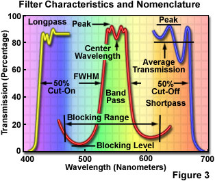
Bandpass filters (Figure 3) transmit a band of wavelengths and block all light above and below the specified transmission range. These filters are characterized with respect to optical performance by their center wavelength (CWL) and bandwidth, also referred to as the full width at half of maximum transmission (FWHM). The center wavelength is calculated from the arithmetic mean of wavelengths at 50 percent of peak transmission, while the bandwidth (FWHM) is the range of wavelengths (in nanometers) measured between the edges of the bandpass curve where light transmission is 50 percent of its peak or maximum value.
Edge filters are also commonly referred to as longpass and shortpass filters (abbreviated LP and SP, respectively), and are cataloged according to their cut-on or cut-off wavelengths at 50 percent of peak transmission (see Figure 3). Longpass filters transmit long wavelengths and block short wavelengths, while shortpass filters have the opposite properties of passing or transmitting short wavelengths while blocking others. Edge filters, in general, have a very steep slope with an average transmission value calculated from the efficiency of transmission and blockage of light in the region of the transition (the boundary between transmission and blocked domains), rather than over the entire spectrum of wavelengths passed or transmitted by the filter. In the past, the terms highpass and lowpass were often used to denote edge filters, but are now discouraged because they more accurately refer to frequency rather than wavelength.
The absorption or transmission profile of filters, a critical element in defining filter action, is usually presented in the form of a wavelength plot (in nanometers; see Figures 1-4) versus the optical density, absorption, or transmission characteristics of the filter. Optical density is defined as the logarithm (base 10) of the absorbance (reciprocal of transmittance) according to the equation:
Where:
And, therefore:
where T is the percentage of light being transmitted through the filter, OD is the optical density, and A is the absorbance value of dyes or other light-absorbing species in the filter. When referring to bandpass or cut-off regions in filters, most manufacturers plot the transmission value, which is the wavelength transmittance percentage, divided by 100, versus wavelength to generate spectral characteristics. However, because filters can block light by means other than absorption, optical density is a more accurate means by which to gauge filter transmission profiles, and is the most commonly used criterion by scientific investigators. In order to avoid confusion, it is important to carefully distinguish whether absorption or transmission values are being employed to characterize filter action over the wavelength range being examined. These should be clearly defined on the ordinate of spectral plots.
Dichroic filters are manufactured by coating either optical-grade or lower quality substrates, including polymers and glass, with thin films in a manner similar to interference filters to achieve specific wavelength transmission characteristics. However, dichroic filters are not as sensitive to the incident illumination angle as interference filters, and they are also not as wavelength-selective. In most cases, the term dichroic is reserved for filters having passbands of 100 nanometers or more with reflected bands being about twice as wide and containing wavelengths comprising the complementary color. Thus, a characteristic of dichroic filters is that they produce different colors when illuminated by reflected or transmitted light. These filters are often utilized as either additive or subtractive color filters for contrast enhancement, machine vision, or color separations. In general, dichroic filters provide a wider aperture than narrow bandpass interference filters and are more suitable for applications that do not involve image formation, such as traditional photographic illumination, printing, and stage lighting.
Measured in units of optical density, the blocking level (also known as the attenuation level) of an optical filter is a measure of the degree to which wavelengths that do not lie in the filter passband are suppressed over an extended range of the spectrum. In conjunction with this concept, the blocking range (or attenuation range) refers to the range of wavelengths in which a filter maintains a specified blocking level (see Figure 3). Also related to the attenuation level of a filter, is a phenomenon known as crosstalk, which defines the minimum attenuation level of two filters placed together in series (stacked back-to-back) with the light beam. The overlap (see Figure 4(a)) between the transmission bands of stacked filters can become important when the spectrum of absorbed or transmitted wavelengths is affected to a significant degree by crosstalk.

The slope of a filter transmission band is utilized to define the steepness of the transition between the wavelengths passed and those blocked by the filter. This profile is especially important in edge filters, which rely on very sharp slopes to define the narrow wavelength boundary regions that separate transmitted wavelengths from those blocked by the filter. As an example, the spectra in Figure 4(b) illustrate two edge filters having significantly differing slopes with associated boundary regions of unequal size, but with similar passbands. In the absence of spectral diagrams, the slope of a filter can be described by identifying the wavelength at a specified blocking or attenuation level.
Cut-off and cut-on values refer to the narrow wavelength region specifying the transition from a high transmission rate to a low transmission (attenuation) rate and vice versa. Cut-off is often employed to indicate wavelength location of a shortpass filter, while cut-on is usually reserved to denote the wavelength location of a longpass filter. In both cases, the wavelength of 50 percent absolute transmission is used to indicate commencement of the transition.
The angle between the optical axis of the filter and the incident light beam is termed the angle of incidence, and can have a significant impact on filter performance, especially with regard to interference filters. A majority of filters are designed to be used for applications having an angle of incidence of zero degrees, termed normal incidence, where the filter is positioned with its optical axis coincident on the optical path of the light beam. However, several types of interference filters, including beamsplitters and dichromatic mirrors, are designed to be positioned at a 45-degree angle with respect to the light beam (an angle of incidence equal to 45-degrees) in order to correctly perform their functions. Glass and polymer absorption filters can be utilized without regard to the angle of incidence, but several types of filters are termed angle-sensitive and have performance characteristics that are heavily dependent upon the incident angle of illumination. These filters, primarily thin-film interference and acousto-optical filters, should not be used at any angle other than that specified by the manufacturer.
Color Compensating, Conversion, and Balancing Filters
Belonging to the category of absorption filters, color compensating, conversion, and light balancing filters are most often utilized to modify the color temperature of tungsten and tungsten-halogen illumination. Kodak manufactures the Wratten series of color compensating and balancing filters, which are designed for a wide spectrum of laboratory and industrial applications. These filters consist of colloidal carbon mixed with suitable dyes and dispersed in gelatin to achieve the desired spectral characteristics. Color compensating filters differ from color balancing and conversion filters in that they control color by attenuating principally the red, green, and/or blue regions of the visible light spectrum rather than fine-tuning overall spectral performance. They are abbreviated with the prefix CC, for Color Compensating, followed by the filter nominal peak density ranging from about 0.025 to 0.5, multiplied by 100, and ending with the capitalized first letter of the filter color (for example: M for magenta). Thus, the abbreviation for a yellow color-compensating filter having a nominal peak density of 0.3 would be: CC30Y. In addition to the Kodak series, a wide variety of similar filters from other manufacturers are available as dyed gels, acrylic polymers, or dichromatic glass.
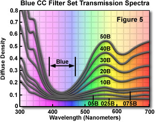
Each color-compensating filter in a series controls the amount of a single color while passing one or both of the remaining two colors. In this manner, color-compensating filters are capable of introducing either subtle changes to the color balance of the light source, or they can compensate for deficiencies in the spectral output. The visible absorption spectra for a series of blue color compensating filters (CC025B through CC50B) are presented in Figure 5. Principal minima appear in the range 380-490 nanometers for all filters in this series, which pass a majority of the blue wavelengths and filter varying amounts of green, yellow, and red wavelengths.
Interference Filters
Recent technological achievements in bandpass filter design have led to the relatively inexpensive construction of thin-film interference filters featuring major improvements in wavelength selection and transmission performance. These filters operate by transmitting a selected wavelength region with high efficiency while rejecting, through reflection and destructive interference, all other wavelengths. Modern interference filters are modeled after the Fabry-Perot interferometer, designed in the late 1800s by Charles Fabry and Alfred Perot, and are constructed with several layers of thin films applied to an optically flat transparent glass surface. The original interferometer consisted of a device having two partially transparent mirrors separated by a small air gap whose size could be varied by translating one or both of the mirrors. Today, more sophisticated interferometers utilize a variety of mechanisms to measure the interference between light beams, and are often employed to monitor thin-film thickness during fabrication of interference filters and mirrors.
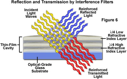
Interference filters can be produced with very sharp transmission slopes, which result in steep cut-on and cut-off transition boundaries that greatly exceed those exhibited by standard absorption filters. To produce modern interference filters, successive layers of dielectric materials, with thickness values ranging between one-quarter and one-half of the target wavelength, are deposited onto an optically flat glass or polymer surface in a vacuum. Light that is incident on the multi-layer dielectric surface is either transmitted through the filter with constructive reinforcement, or reflected and reduced in magnitude by destructive interference (see Figure 6). The filter bandpass, which is determined by the nature of the layered dielectric surface, determines the wavelengths of light that are allowed to be transmitted and multiply reflected when passing through the filter. Blocked wavelengths that not reinforced and passed by the filter are reflected away and removed from the optical path.
The dielectric materials utilized to fabricate interference filters are generally nonconductive materials having a specific refractive index. Traditional bandpass interference filters are manufactured using zinc sulfide, zinc selenide, or sodium aluminum fluoride (also termed cryolite), but these coatings are hygroscopic and must be insulated from the environment by a protective coating. In addition, the zinc and cryolite salts suffer from low filter transmission characteristics and temperature instability, which further reduces their performance, even though they are simple and relatively cheap to manufacture. After deposition of the thin film salt layers, a final layer of glass or an abrasion-resistant protective coating of silicon monoxide is added.
Introducing semi-transparent layers of metal oxides (known as hard coatings) into thin-film coating technology has alleviated many of the environmental problems associated with interference filters, and dramatically improved their temperature stability. The thin coatings of metals and salts, each with a unique refractive index, are applied in successive layers having alternating high and low refractive index values. The critical element of this design is the interface between two dielectric materials of differing refractive index (one much higher than the other), which is responsible for partially reflecting incident light forward and backward through the filter and producing the interference effect that results in wavelength selection. Reinforced and transmitted wavelength values are determined by the thickness and refractive index of the interspersed dielectric layers. Even though the thin coatings themselves are transparent, light waves reflected and transmitted by the dielectric materials interfere to produce brilliant colors that appear to be emanating from the filter surface.
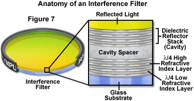
Dielectric coatings are often bundled into units termed cavities, which are constructed of three to five alternating salt and metal oxide (and sometimes pure metal) layers separated by a wider layer of magnesium fluoride termed a spacer (see Figure 7). The spacers are produced with a thickness that corresponds to even multiples of a quarter or half wavelength in order to reflect or transmit light in registration with the dielectric layers. Increasing the number of cavities utilized to build an interference filter produces a proportional increase in the slope of the cut-on and cut-off wavelength transmission boundaries. Filters featuring up to 15 stacked cavities can have a total of over 75 individual dielectric layers and display bandwidths only a few nanometers in size.
Virtually any type of filter can be designed and constructed with thin-film interference coating technology, including bandpass, shortpass, longpass, dichroic beamsplitters, neutral density, and a variety of mirrors. As discussed above, the number of layers and cavities is utilized to control, with very high precision, the nominal wavelength, bandwidth, and blocking level of the filter. Filters with multiple transmission bands, such as the complex triple-band filters so popular for fluorescence microscopy (see Figure 1), can be fabricated with this technique.
The high degree of blocking obtained with thin-film interference filters only applies to a finite wavelength range, beyond which effective blocking drops off dramatically. The range can be extended by adding auxiliary components, such as wideband blockers, but often at a compromise in peak transmission values. In addition, the coating materials utilized in thin-film production are limited in their range of transparency. Once the range has been exceeded, these coatings can become highly absorbing rather than highly reflecting or transmitting, thus reducing the efficiency of the filter. Coating absorption characteristics can also be wavelength-dependent, so the same coating utilized for longpass filters will usually not perform adequately at lower wavelengths in the violet and ultraviolet region. Finally, interference thin-film coatings are sensitive to the incident angle of illumination. As this angle is increased, the spectral characteristics of the coating tend to shift towards shorter wavelengths (the spectrum is blue-shifted). Another drawback is that interference coatings often produce polarized light at high incident angles, an effect that is not always desirable. Regardless of the deficiencies found in thin-film coatings, this technology is still one of the most suitable for wavelength selection in a wide variety of applications.
Neutral Density Filters
Extensively utilized in a variety of applications, neutral density filters are neutral gray in color (resembling smoked glass) and are designed to reduce transmitted light intensity evenly across either a small number of wavelengths or the entire wavelength spectrum without altering the spectral profile of illumination. Neutral density filters are ideal for controlling the intensity of illumination in the optical microscope, where they are commonly employed in brightfield, differential interference contrast, and fluorescence illumination (in which the high intensity arc lamps cannot be regulated with an adjustable power supply to control voltage).
Neutral density filters are divided into two classes: absorptive and reflective, which work by absorbing or reflecting a selected band of wavelengths (or the entire visible light spectrum), respectively. Absorption neutral density filters are constructed from an emulsion of rare earth elements impregnated throughout the glass, and can be used in any orientation with respect to the illumination source. These filters are impervious to scratches, and do not require the careful handling techniques necessary for gelatin, polymer, reflective, and other less-resilient filters. Reflective neutral density filters are manufactured by evaporating a thin coating of metal onto one of the glass surfaces, and must be inserted into the optical path with the reflecting surface facing the illumination source. Because the surface coating is prone to scratches and abrasions, these filters should be carefully handled.
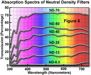
Presented in Figure 8 are the visible light absorption profiles for a series of common neutral density filters. As can be seen in the figure, these filters display a relatively constant extinction coefficient throughout the visible light (400 to 700 nanometers) spectral range. Each neutral density filter in the series, ranging from ND-0.3 to ND-70 in Figure 8, has an incrementally lower extinction coefficient. This filter set collectively provides a uniform series of filters for adjusting illumination intensity.
Absorptive neutral density filters are manufactured using gelatin, polymeric, or glass substrates that have impregnated or dissolved materials to reduce transparency. Kodak Wratten neutral density filters are very popular, and are made with the proprietary gelatin thin films for which these filters are known. A colloidal carbon suspension containing a selected complement of organic dyes is mixed with liquid gelatin until the desired neutral density is achieved. This combination is then coated onto a supportive glass substrate until it forms a very thin film of uniform thickness. After drying, the film is stripped from the substrate and coated with lacquer for protection. Note that even though neutral density, color compensating, and other Wratten filters are protected by a lacquer overcoat, they are still susceptible to damage (particularly from scratches), and should be handled only at the edges or in the corners. An alternative is to protect gelatin filters by placing them into a simple metal frame, marketed by a number of manufacturers. Never expose gelatin filters to temperatures exceeding 50 degrees Celsius for extended periods. It is also important that these filters not be placed too close to the tungsten-halogen lamp of a microscope, or other instrument, to avoid heat damage.
Specifications for the most commonly utilized neutral density filters are listed in Table 1. Each neutral density filter is designated by an alphanumeric code, ND-XX, where XX is the average light percentage transmitted by the filter. Thus, an ND-60 filter transmits (or passes) 60 percent of the incident light from the illumination source, and a ND-0.1 filter transmits 0.1 percent of the incident light.
Neutral Density Filter Specifications
|
|||||||||||||||||||||||||||||||||||||||||||||||
Table 1
Neutral density filters can be stacked together to achieve density values for which there is no available filter. Stacking of these filters is an additive effect, so that placing a ND-50 (density = 0.3) and ND-60 (density = 0.2) filter into the light path is equivalent to such placement of a ND-30 (density = 0.5) filter. A filter with a density of 0.30 has a transmittance of 50 percent (ND-50, Table 1), so it can be used to reduce the illumination intensity by a factor of two. Likewise, a filter having a density of 0.6 (ND-25, Table 1) has a transmittance value of 25 percent (reduces illumination intensity by a factor of four), and a filter of density 1.0 (ND-10.0, Table 1) can reduce intensity by a factor of 10 (transmittance value of 10 percent).
Older neutral density filters may acquire a slight yellowish tinge with age, and some of the cheaper filters may also display some degree of background color. If the introduction of neutral density filters into the optical pathway results in incorrect color balance, use color-compensating filters to return the light source to its proper balance. Other factors, such as internal scattering and reflections in the optical system, can alter the effective density of neutral density filters, causing them to vary from the expected density values. For this reason, it is important to calibrate neutral density filters for critical measurements.
Ultraviolet and Infrared Filters
High-energy arc lamps, flash tubes, and other illumination sources often produce a significant amount of ultraviolet light that may interfere with imaging, either using traditional photographic film or when capturing digital images. Ultraviolet filters can be inserted into the light path of microscopes and other optical systems to remove unwanted wavelengths residing beneath those in the visible light spectrum (below 400 nanometers). The most common ultraviolet filters are designed to be installed on the front of camera lenses or CCD sensors, but microscope, telescope, and aftermarket manufacturers also offer these filters for a variety of specific applications. A majority of the ultraviolet filters are made from specialized glass formulations, but newer polymeric materials are also available. Optical grade ultraviolet longpass filters made from transparent flexible films can be cut to size and used in combination with other bandpass filters.
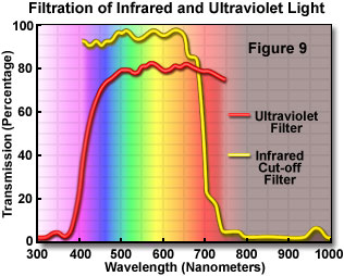
Infrared cut-off filters are designed to pass visible wavelengths between 400 and 700 nanometers while blocking higher wavelengths extending into the infrared region (700 to 2500+ nanometers). These filters are often utilized to protect infrared-sensitive charge-coupled device (CCD) and complementary metal oxide semiconductor (CMOS) image sensors from infrared wavelengths. In contrast, infrared longpass filters are employed for applications that require blocking of visible light, while passing near-infrared wavelengths. New polymeric materials are being developed that have excellent characteristics for transmitting selected bands of infrared. In particular, thermoset ADC filters have very high transmission values and low haze, with significant abrasion and chemical resistance, making them ideal shortpass and longpass filters for infrared applications. Figure 9 illustrates the spectral response of both an ultraviolet filter that attenuates wavelengths almost completely below 400 nanometers, and an infrared cut-off filter with very strong absorption of wavelengths above 700 nanometers.
Almost 90 percent of the radiation emitted by a tungsten or tungsten-halogen lamp occurs in the form of infrared wavelengths, which is associated with the production of heat. Mercury and xenon arc lamps also produce a considerable amount of heat. Infrared-absorbing or heat filters can be utilized to remove unwanted infrared wavelengths and protect color correcting gels, neutral density filters, expensive interference filters, and the object being photographed, from heat damage.
Some heat-absorbing filters are made from a special type of Pyrex glass known as Aklo or Schott KG-1, which absorbs infrared heat rays, and then dissipates the heat into the air surrounding the glass. Filters made with Aklo or KG-1 are often green or blue-green in color and may introduce color balance deviations into photographs or digital images. For traditional photography with films, this side effect can be corrected with color compensating filters that are complementary to the heat-absorbing filter color. A close approximation to the appropriate correction can be obtained by placing various complementary filters on top of the heat filter until one is found that exactly balances the color tinge of the heat filter and turns the color to a neutral value. Alternatively, in digital photography, the white balance function of a digital camera can be set with the filter in place to avoid color shifts.
Specialized dichromatic interference filters, known as hot mirrors, are sometimes employed to protect optical systems by reflecting heat back into the light source. Designed to be utilized at an incidence angle of zero degrees, these reflecting mirrors are useful in a variety of optical applications where heat build-up can damage components or adversely affect spectral characteristics of the illumination source. In contrast, cold mirrors operate over a very wide temperature range to reflect the entire visible light spectrum while very efficiently transmitting infrared wavelengths. Mirror filters are constructed with multi-layer dielectric coatings, in a manner similar to interference filters, which are evaporated in successive layers onto a glass surface. Wavelengths reflected by an infrared hot mirror range from about 750 to 1250 nanometers.
A high-performance filter type in this class, extended hot mirrors, cover a wider range of infrared wavelengths, generally up to 1750 nanometers. Hot mirrors and extended hot mirrors produce excellent results when coupled with high-intensity tungsten-halogen bulbs in fiber optic illuminators to reduce heat without sacrificing the visible output of the lamps. In general, hot mirror filters are far more efficient at blocking heat than quartz or glass heat absorbing filters, and will not crack or break, even when a significant amount of heat is incident on the filter surface. However, most manufacturers recommend relieving heat build-up in areas adjacent to hot mirrors by placing a cooling fan close to the mirror housing.
High-Performance Filters
Recent advances in filter technology have yielded several sophisticated devices that feature superior performance when compared to classical absorption or interference filters, especially when utilized with laser illumination sources. Acousto-optical tunable filters (abbreviated AOTF; see Figure 10) operate by irradiating a specially prepared crystal, such as tellurium oxide or quartz, with radio wave acoustical vibrations generated by a high-frequency transducer. The result is to create the equivalent of a bulk transmission diffraction grating for light waves passing through the crystal. The filter can be tuned by varying the frequency of exciting radio waves, which enables only a very narrow band of wavelengths (often between 1 and 3 nanometers wide) to pass and eliminates the remainder by diffraction.
A major advantage of acousto-optical filters is their ability to perform wavelength scanning at rapid rates simply by changing radio frequencies, and to pass several wavelengths that are widely separated by mixing multiple excitation frequencies. In addition, the intensity of light passed through the filter can be adjusted by altering the amplitude of acoustical vibrations from the transducer. A disadvantage is that light intensity is severely reduced in broad wavelength sources due to selection of only one or a few wavelengths. In addition, the device produces linearly polarized light, and will result in (at least) a 50-percent reduction in transmission when non-polarized incident light is radiated from the source.
A second electronically controlled device, the liquid crystal tunable filter (LCTF), is being increasingly utilized as an emission filter in optical microscopy due to the wide aperture and the ability to conduct imaging-quality filtering. These filters can also rapidly select wavelengths and have adjustable attenuation. In addition, liquid crystal filters offer a choice of bandwidths and blocking levels, and do not exhibit image-shift artifacts coupled to wavelength. Disadvantages include production of polarized light by these filters, so that peak transmission for non-polarized light is usually somewhat less than 50 percent.

A typical wavelength-selective liquid crystal tunable filter is constructed from a stack of fixed filters consisting of interwoven birefringent crystal/liquid-crystal combinations and linear polarizers. The spectral region passed by LCTFs is dependent upon the choice of polarizers, optical coatings, and the liquid crystal characteristics (nematic, cholesteric, smectic, etc.). In general, visible-wavelength devices of this type usually perform quite well in the 400 to 700 nanometer region.
Cleaning and Maintaining Filters
Filters are optical components that are very susceptible to damage by contamination from dust, dirt, fingerprint oils, and fibers, and should be handled very carefully to avoid scratches. Glass, acrylic polymer, thin-film interference, and antireflective-coated surfaces can be damaged by abrasive particles that come into contact with the filter. Gelatin filters are protected by a thin lacquer coating and should be handled only at the edges or corners. When not in use, filters should be stored in their original packaging, in protective cases, or interleaved with clean lens-cleaning paper for protection. Gelatin filters must not be brought into contact with water and should be kept in the dark under low-humidity conditions when being stored. In the event filters must be utilized in high temperature climates that have relatively high humidity, protect the filters from fungal damage by storing them in desiccated, hermetically sealed containers.
Gelatin, polymeric, and glass filters should be cleaned by gently brushing away loose dust, dirt, and fibers with a clean, dry camelhair brush. Filters can also be cleaned by blowing clean, dry air or inert gases (available in aerosol cans) across the surface. Avoid using aerosol cans that have Freon or similar propellants, which can liquefy on the filter or chill the surface allowing atmospheric water to condense. In addition, some aerosols have a propellant that can leave a residue on the filter surface, which can be more difficult to remove than the original contaminants. An ear syringe (rubber balloon) can also be employed to blow dust and dirt from filter surfaces. All filters should be periodically cleaned, especially when used on a daily basis.
In the event contamination cannot be easily removed with a brush or by flowing air across the surface, use lens cleaning tissue or a Kimwipe moistened in lens cleaning solvent or ethanol to remove debris and oils. Use enough paper to keep solvents from dissolving oils in the fingers and transferring these solvated oils onto the filter surface. Do not allow the liquid cleaner to come into contact with the edges of the filter. Always remove as much contamination as possible with the brush or rubber balloon before using paper on filter surfaces to avoid grinding the debris into the filter. If available, use cloth or powder-free gloves while handling filters to prevent fingerprints from contaminating the surface. The surfaces of some interference filters are extremely susceptible to scratches and should never be cleaned with paper tissue.
Interference filters are very fragile and gradually deteriorate when exposed to intense ultraviolet radiation (from mercury and xenon arc lamps), moisture, and heat. In addition, these filters are prone to scratches, even with delicate handling, and can be destroyed by oils in fingerprints and exposure to even mild chemicals. Loose deposits and mild fingerprints can be removed with a lens tissue and neutral (not acidic) lens cleaner, but care should be taken not to apply too much pressure to the surface.
Filters mounted between optical glass plates are more resistant to scratches than gelatin filters, but they should still be stored in protective cartons and kept in dry, low-humidity areas. Gelatin filters sandwiched between glass plates must be carefully cleaned. Never wash these filters in water or detergents, even when the edges have been protected by a coating to resist entry of moisture. Small imperfections in protective coatings can enable water to come into contact with the gelatin filter at the glass edges, causing the filter to swell and separate from the glass plates. Gelatin filters can often be permanently stained by water.
Avoid subjecting filters to high temperatures by placing them too close to intense heat-producing lamps. Kodak recommends that Wratten gelatin filters not be subjected to temperatures higher than 50 degrees Celsius (122 degrees Fahrenheit) for long periods of time. Because individual filter dyes respond differently when exposed to heat and light for identical periods of time, some filters will degrade more rapidly than others. For this reason, manufacturers have compiled a list of Filter Stability Classes, which are utilized to organize filters according to their resistance to heat and light damage. In establishing these classifications, each filter is exposed to a selected light source for a specific time interval at a series of temperatures. The extent of changes in dye density, measured with a precision spectrophotometer, is then expressed as a fraction or multiple of the difference between the light and dark limits that define acceptability in the spectral region spanning 400 to 700 nanometers (visible light).
Filters are classified as being stable if they show a change no greater than one-half of the difference between the limits when subjected to illumination exposure tests. A rating of relatively stable is given to filters that display a change equal to the difference between the limits. Somewhat stable filters demonstrate a change greater than the difference between the limits, but not more than twice this difference. If a filter shows change greater than twice the limits, it is classified as unstable. Filter stability can vary from test to test. For example, a filter classification of ABA indicates the filter is stable to the daylight exposure test, is relatively stable when tested under extremely intense artificial illumination, and is also stable to the high-intensity tungsten lamp test. For critical applications, filters should be routinely inspected using a spectrophotometer and replaced if the absorption spectrum deviates more than a couple of percent. Frequent visual inspections can reveal if degradation is occurring in the form of fading in the central portion of the filter, which normally receives the most exposure to radiation.
Successful use of filters requires attention to the technical details of absorption and transmission spectra, as well as other published filter characteristics. The key is to build a solid base of facts surrounding the physical properties of the light source, digital imaging or traditional photography criteria, and the effects of the filters obtained while acquiring solid experience with real-world applications. Some filters are used purely for technical applications, while others are implemented for their artistic qualities. Regardless of the target function, proper use of filters will dramatically improve the quality of photography using conventional film, as well as electronic digital imaging.
Contributing Authors
Douglas B. Murphy - Department of Cell Biology and Microscope Facility, Johns Hopkins University School of Medicine, 725 N. Wolfe Street, 107 WBSB, Baltimore, Maryland 21205.
Kenneth R. Spring - Scientific Consultant, Lusby, Maryland, 20657.
Michael W. Davidson - National High Magnetic Field Laboratory, 1800 East Paul Dirac Dr., The Florida State University, Tallahassee, Florida, 32310.