Interactive Java Tutorials
Birefringent Polarizing Prisms
Polarizing prisms are utilized in a wide spectrum of applications ranging from optical microscopy and spectroscopy to complex laser systems. This interactive tutorial explores how various common birefringent polarizing prisms operate to split light waves into ordinary and extraordinary components.
The tutorial initializes with a Glan-Foucault polarizer appearing in the window having a beam of non-polarized light incident on the left-hand prism face. Upon passing through the prism and encountering the glass/air interface between the first and second prisms, the light beam is separated into extraordinary and an ordinary wave components (the E-Ray and O-Ray, respectively). The optical axis of each prism composing the polarizer is indicated with a two-ended arrow. In order to select another polarizer configuration, click the mouse cursor on the Polarizing Prism pull down menu. The speed of the light beam traversing the polarizer can be altered with the Applet Speed slider.
Scottish physicist William Nicol first devised a polarizing prism in 1828 by cutting a rhombohedral section of the mineral calcite (Iceland spar) diagonally, polishing the cut surfaces, and cementing them back together with Canada balsam. The result is a transparent birefringent crystal, known as a Nicol prism, which effective separates polarized light at the interface between the two crystal halves. Upon entering the prism through one of the smaller angled legs (parallel to the long axis of the crystal), non-polarized light is split into two polarized components, termed the ordinary and extraordinary waves, which traverse the crystal at different speeds. The two separated light waves also have their electric vector vibration directions positioned at a 90-degree angle with respect to one another. When the interface between the two crystal sections is encountered by the separated light waves, the ordinary component is refracted to a much greater degree and is absorbed by a layer of black paint applied to the outer surface of the prism. In contrast, the extraordinary ray passes through the interface and emerges from the prism slightly displaced, but still traveling in a direction that is parallel to the incident light. The resulting plane-polarized light can be utilized to illuminate birefringent specimens in a microscope or any other device that requires the input of light having electric field vibrations restricted to a single plane.
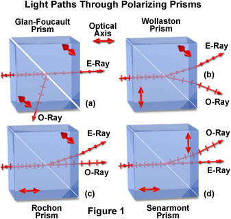
Common variations of the Nicol prism include the Glan-Foucault polarizer (See Figure 1(a)), which consists of two identical prisms of calcite cut with the optical axes parallel to the corner edges, and mounted with a small air gap so that the long crystal faces are parallel to one another. This prism is transparent to wavelengths ranging from about 230 nanometers, in the ultraviolet region of the spectrum, to over 5000-nanometer infrared radiation. Such a broad wavelength transmission range enables Glan-Foucault prisms to be utilized in a variety of instruments. Like the Nicol prism, incident light striking the Glan-Foucault prism is separated into ordinary and extraordinary waves that are vibrating either parallel or perpendicular to the optical axis. However, in this case, the divided light waves travel through the prism without refraction until they encounter the glass/air boundary, whereupon the ordinary ray is totally internally reflected, but the extraordinary ray passes through the boundary with only a slight deviation.

If the crystal halves are cemented together, the prism is then referred to as a Glan-Thompson polarizer (or prism), and can withstand more intense radiation, such as that from a high-intensity laser source. A third birefringent prism is known as the Wollaston prism, which is really a polarizing beamsplitter made from two calcite or quartz sections cemented together with the optical axes oriented orthogonally (Figure 1(b)). Polarized light passing through a Wollaston prism is separated into orthogonal waves, as described above for the other polarizing prisms. However, when the ordinary and extraordinary waves encounter the diagonal cement junction, they exchange identities, are refracted in different directions, and emerge from the prism slightly displaced from one another. The deviation angle (often termed the shear) between the two exiting light waves is determined by the wedge angle of the prism, which is usually varied between 15 and 45 degrees.
Several derivatives of the Glan-style prisms can be produced by altering the orientation of calcite or quartz optical axes with respect to the individual crystal halves (as illustrated in Figure 1). The Rochon prism (Figure 1(c)) positions the axes orthogonally to each other and is arranged so that incident non-polarized light enters the prism parallel to the optical axis (and is not separated). When light waves pass through junction in a Rochon prism, they enter a new region where the optical axis is oriented perpendicular to the waves. This causes the light to be split into ordinary and extraordinary components, with the ordinary wave passing through undeviated and the extraordinary wave being refracted away from the perpendicular. The reverse scenario can be achieved with a Senarmont prism, which also has the axis of the first crystal section oriented parallel to incident illumination. However, when the light waves encounter the boundary in a Senarmont prism (see Figure 1(d)), the orientation of the optical axis in the second half of the prism allows the extraordinary ray to pass through undeviated, but refracts the ordinary wave. These prisms can be utilized to select individual orientations of polarized light for specific optical applications.
Contributing Authors
Matthew J. Parry-Hill and Michael W. Davidson - National High Magnetic Field Laboratory, 1800 East Paul Dirac Dr., The Florida State University, Tallahassee, Florida, 32310.
BACK TO PRISMS AND BEAMSPLITTERS
