
Interactive Java Tutorials
Dielectric Plate Beamsplitters
A beamsplitter is a common optical component that partially transmits and partially reflects an incident light beam, usually in unequal proportions. In addition to the task of dividing light, beamsplitters can be employed to recombine two separate light beams or images into a single path. This interactive tutorial explores transmission, reflection, and total internal reflection exhibited by a light beam interacting with a dielectric plate beamsplitter.
The tutorial initializes with a dielectric-coated plate beamsplitter positioned with an incident light wave impacting the planar front surface at a 45-degree angle to the direction of propagation. In order to operate the tutorial, use the mouse cursor to translate the Angle of Incidence slider between a range of 45 and 90 degrees. As the slider is moved from left to right, the angle of incident light changes to the value displayed above the slider bar. Simultaneously, the angle of reflected and transmitted light waves also changes, as does the total internal reflection angle of light captured within the glass slide.
The simplest configuration for a beamsplitter is an uncoated flat glass plate (such as a microscope slide), which has an average surface reflectance of about 4 percent. When placed at a 45-degree angle, the plate will transmit most of the light, but reflect a small amount at a 90-degree angle to the incident beam. Plate beamsplitters are, as the name implies, optical crown glass plates having a partially silvered coating designed to produce a desired transmission-to-reflection ratio. These ratios usually vary between 50:50 and 20:80, depending upon the application.
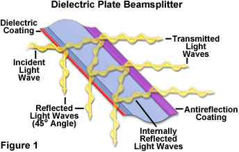
In general, a metallic or dielectric film is deposited on the first surface (facing the incident illumination) of the beamsplitter plate, while an antireflection coating is applied to the back (Figure 1). Antireflection coatings can be chosen to match the incident angle of light in order to minimize the amount of light reflected from the rear surface of the plate and reduce the possibility of ghost images. Typical antireflection coatings display only about 0.5 percent reflectivity at an incident angle of 45 degrees. Dielectric coatings must also be fine-tuned to produce the proper reflectance, polarization properties, and wavelength distribution at the angle for which the beamsplitter is designed. Because both dielectric and antireflection coatings have negligible absorbance in the visible light region (typically 0.5 percent for a 50/50 beamsplitter at 45 degrees), plate beamsplitters are ideal for a wide spectrum of applications.
One of the most serious consequences of using dielectric coatings for beamsplitter fabrication is the unequal transmission and reflection for p and s (parallel and perpendicular) polarization components of non-polarized incident light beams. As a result, some dielectric beamsplitters divide light unequally according to the polarization content, which can be undesirable in many applications. When using dielectric coatings, this artifact can often be circumvented by altering the polarization vector orientation of the incident light. In addition, the polarization effect can be reduced through the utilization of more sophisticated multi-layer thin-film dielectric coating designs, but often at the expense of other performance aspects.
Specialized non-polarizing beamsplitter coatings have been designed for use with polarized laser light where the incident radiation must maintain its polarization direction in both the transmitted and reflected beams. The coatings can effectively produce a clean 50/50 split of laser energy, regardless of the polarization state of the incident beam. As a side advantage, non-polarized light incident on these coatings has both the parallel and perpendicular components transmitted at almost equal ratios. Plate beamsplitters can also be designed to act as longpass and shortpass edge filters (positioned at a 45-degree angle) for applications requiring specific wavelength selection. In the case of longpass filters, longer wavelengths are transmitted and shorter wavelengths reflected at a 90-degree angle to the incident beam. Shortpass filters act in a reverse manner (transmit short wavelengths and reflect long wavelengths). Beamsplitters acting as edge filters are often referred to as dichroic or dichromatic mirrors.
Plate beamsplitters have some advantages when compared to cube beamsplitters, primarily the lack of an optical cement in the vicinity of the dielectric or metallic film, which can absorb light energy and reduce transmission. As a consequence, plate beamsplitters can withstand significantly higher levels of radiation without suffering damage. Single glass plates are also much smaller and lighter than a twin-prism cube, and can be more easily fitted into tight spaces for compact optical configurations.
Contributing Authors
Matthew J. Parry-Hill and Michael W. Davidson - National High Magnetic Field Laboratory, 1800 East Paul Dirac Dr., The Florida State University, Tallahassee, Florida, 32310.
BACK TO PRISMS AND BEAMSPLITTERS