Interactive Java Tutorials
Birefringence Variations with Crystal Orientation
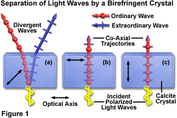
When a beam of light is incident on a birefringent crystal, the waves are split upon entry into orthogonal polarized components (termed ordinary and extraordinary) that travel through the molecular lattice along different pathways, depending on their orientation with respect to the crystalline optical axis. If the incident beam is oblique to the optical axis, the waves diverge during their journey through the crystal. In contrast, the orthogonal wave components follow a co-linear pathway when the incident light beam enters the crystal either parallel or perpendicular to the optical axis. This interactive tutorial explores variations in birefringence that result from orientational variations between the crystal optical axis and the incident light beam.
The tutorial initializes with a crystal (represented by a blue rectangular block) appearing in the window, and having the optical axis oriented North-South (up and down in the tutorial). An incident polarized light beam (yellow line with short crossbars) oriented at a 45-degree angle enters the crystal from the lower face and is split into orthogonal components. The ordinary wave passing through the crystal is represented by a red line with periodic dots (wavefronts), while the extraordinary wave is denoted by a blue line with periodic crossbars (also intended to represent wavefronts). The Refractive Index slider is used to vary the refractive index of the virtual crystal between a value of 1.5 (crown glass) and 1.7 (flint glass). As the slider is translated to the right, the refractive index increases, which causes the velocity of the wavefronts traveling through the crystal to decrease.
When the incident light beam enters the crystal parallel to the optical axis (default setting), the ordinary and extraordinary wavefronts coincide in amplitude, phase, and trajectory during their journey through the crystal. After rotating the optical axis to an oblique position with respect to the incident beam using the Crystal Orientation slider, the split orthogonal waves diverge and follow different pathways through the crystal. In addition, the ordinary wave begins to travel faster than the extraordinary wave. The divergence angle grows with increasing obliquity of the optical axis, until the axis reaches 45 degrees (maximum divergence) with respect to the incident beam. Translating the slider still farther reduces the divergence angle as the optical axis slowly becomes perpendicular to the incident light beam. When the crystal optical axis is exactly perpendicular (90 degrees) to the incoming polarized light waves, the divergence between orthogonal waves is eliminated, but the ordinary wave still travels through the crystal at a higher rate of speed than does the extraordinary wave.

As discussed above, the incident light rays giving rise to the ordinary and extraordinary rays enter the crystal in a direction that is oblique with respect to the optical axis, and are responsible for the observed birefringent character. The behavior of an anisotropic crystal is different, however, if the incident light enters the crystal in a direction that is either parallel or perpendicular to the optical axis, as presented in the tutorial and Figure 1. When an incident ray enters the crystal perpendicular to the optical axis, it is separated into ordinary and extraordinary rays, as described above, but instead of taking different pathways, the trajectories of these rays are coincident. Even though the ordinary and extraordinary rays emerge from the crystal at the same location, they exhibit different optical path lengths and are subsequently shifted in phase relative to one another (Figure 1(b)). The two cases just described are illustrated in Figure 1(a), for the oblique case, and Figure 1(b) for the situation where incident light is perpendicular to the optical axis of a birefringent crystal.
In the case where incident light rays impact the crystal in a direction that is parallel to the optical axis (Figure 1(c)), they behave as ordinary light rays and are not separated into individual components by an anisotropic birefringent crystal. Calcite and other anisotropic crystals act as if they were isotropic materials (such as glass) under these circumstances. The optical path lengths of the light rays emerging from the crystal are identical, and there is no relative phase shift.
Although it is common to interchangeably use the terms double refraction and birefringence to indicate the ability of an anisotropic crystal to separate incident light into ordinary and extraordinary rays, these phenomena actually refer to different manifestations of the same process. The actual division of a light ray into two visible species, each refracting at a different angle, is the process of double refraction. In contrast, birefringence refers to the physical origin of the separation, which is the existence of a variation in refractive index that is sensitive to direction in a geometrically ordered material.
Contributing Authors Douglas B. Murphy - Department of Cell Biology and Microscope Facility, Johns Hopkins University School of Medicine, 725 N. Wolfe Street, 107 WBSB, Baltimore, Maryland 21205. Kenneth R. Spring - Scientific Consultant, Lusby, Maryland, 20657. Matthew J. Parry-Hill and Michael W. Davidson - National High Magnetic Field Laboratory, 1800 East Paul Dirac Dr., The Florida State University, Tallahassee, Florida, 32310.
BACK TO POLARIZED LIGHT MICROSCOPY
