
Interactive Java Tutorials
Birefringence in Calcite Crystals
As light travels through an anisotropic material, the electromagnetic waves become split into two principal vibrations, which are oriented mutually perpendicular to each other and perpendicular to the direction that the waves propagate. The wave whose electric vector vibrates along the major axis of the index ellipse is termed the slow wave, because the refractive index for this wave is greater than the refractive index for the other wave. The wave vibrating perpendicular to the slow wave is termed the fast wave. This tutorial explores double refraction or birefringence in calcite (calcium carbonate), a colorless, transparent, rhombohedral crystalline salt that is the most common such material found naturally.
The tutorial initializes with a calcite crystal positioned in the center of the window, and superimposed over letters for the word Birefringence. Due to birefringence in the calcite crystal, letters seen through the mineral appear doubled. As the crystal is rotated with the Rotate Crystal slider, one of the images remains stationary while the other precesses around the first. The mouse cursor can be used to drag and drop the virtual calcite crystal to any location within the tutorial window. When the crystal is placed on the symbols, bar sets, or dotted lines in the window, an identical effect is observed. The Enable Polarizer checkbox adds a virtual polarizer (positioned over the calcite crystal) to the tutorial. After the polarizer is activated, use the Rotate Polarizer slider to rotate the polarizer transmission axis through 360 degrees and observe how the text or symbols oscillate in position.
A popular demonstration of birefringence is effected by taking a piece of white paper having a single letter A drawn on the paper, and covering the letter with a small crystal of calcite (as illustrated in the tutorial and in Figure 1(b)). When the calcite crystal is placed on top of the letter, the image observed through the crystal is doubled. As the crystal is slowly rotated about the letter, one of the images of the letter remains stationary, while the other precesses around the first.
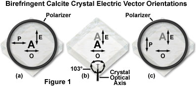
Presented in Figure 1(b) is the double image of the letter A observed through a calcite crystal. As the crystal is turned, the extraordinary (E) ray image precesses around the ordinary (O) ray image. The extraordinary wave vibrates in the plane that includes the c axis (the principle section through the crystal), while the ordinary wave vibrates perpendicular to this axis. The optical axis of the crystal is indicated by c, which in calcite, represents the axis of threefold symmetry. The optical axis makes an equal angle with all three of the crystal faces that join at the two corners, where all edges lie at 103-degree angles with each other. The c-axis lies in the direction of the semi-ionic bond that links the planar carbonate groups and calcium atoms in the calcite (calcium carbonate) lattice.
The phenomenon of image splitting and precession is explained by the birefringence of calcite. In fact, birefringence in calcite is so strong that not only are there two waves, but even the directions of the two waves become separated. One of the waves, the ordinary ray, travels straight through, with its image remaining stationary when the crystal is turned. This ray is termed the ordinary ray because it behaves (is refracted) in an ordinary fashion. The other wave, the precessing one, refracts in an extraordinary fashion, and is thus termed the extraordinary ray.
A useful tool for examination of polarized light is a pair of Polaroid sunglasses, which contain inexpensive sheets of polarized lens material. In ordinary light, these sunglasses show no apparent anisotropy, even when they are oriented in different directions. However, if one observes the surface of a body of water or the glare on a road or painted surfaces, the polarized reflected light is removed by the polarized lens material. Light that is reflected from the water surface (or other non-conducting material) is plane-polarized, especially at a particular angle of incidence, often termed the Brewster angle. Light reflected at the Brewster angle is polarized so the electric vector is vibrating parallel to the surface from which it was reflected, not perpendicular to that surface.
This behavior can be explained from a series of equations by Fresnel, but perhaps an easier method is to employ the stick model first proposed by Robert W. Wood. Consider a stick of wood in place of the electric vector. If the wood impacts a water surface at an angle, the stick slides into the water and is not reflected. However, if the stick lands parallel to the water surface, it can bounce back. Because in nature, horizontal surfaces are almost exclusively encountered, it will be a horizontal vibration that is reflected. To minimize or cut glare, Polaroid sunglasses are designed to remove the horizontal vibrations and transmit the electric vector that is vibrating vertically. Thus, polarized sunglasses, or the simple polarizing elements derived from them, represent a useful standard for transmission of the electric vector (see Figure 1).
The concept of utilizing transparent polarized materials to determine the electric vector directions for the extraordinary and ordinary rays in calcite is presented in Figure 1(a) and (c). When the polarizing elements are oriented so that light waves having electric vectors in the vertical direction are transmitted, those waves having similar vectors in the horizontal direction are absorbed. Polarizers superimposed over calcite crystals in Figure 1(a) and (c) are oriented so that the vertical electric vectors are transmitted. The calcite crystal in Figure 1(a) is oriented so that the extraordinary ray is transmitted, but the ordinary ray is absorbed by the polarizer. At an intermediate angle (not illustrated), both images are partially transmitted following the cosine squared law.
Returning to the calcite crystal, the image of the letter A in Figure 1(a) has a vertical extraordinary ray vector, and therefore, when viewed through a polarizer with vertical orientation, the bottom image (the letter A transmitted by the ordinary ray) will disappear. If either the crystal or polarizer is turned slowly, two images appear until the rotation angle reaches 90 degrees (Figure 1(c)). At this point the letter A formed by extraordinary light waves disappears and the one formed by ordinary light waves reaches its brightest intensity. Thus, with birefringence, a light beam is split into two waves traveling at different velocities, perpendicular to each other. Upon closer inspection, the image formed by the extraordinary ray appears farther through the crystal than the ordinary ray image, which indicates that the ordinary ray image has suffered greater refraction. In other words, the refractive index experienced by the extraordinary ray is less than that for the ordinary ray in calcite.
Calcite crystals can be used as very effective polarizers. In fact, Nicol, Glan-Thompson, Ahrens, and other prisms are made of calcite to isolate and transmit only one of the polarized waves. It is unfortunate that the wave transmitted by these otherwise superior polarizing materials is the extraordinary wave. The velocity of the extraordinary wave (or refractive index of the extraordinary ray) varies with direction of propagation. Calcite prisms introduce astigmatism unless all the beams travel parallel to each other through the crystal.
Contributing Authors
Douglas B. Murphy - Department of Cell Biology and Microscope Facility, Johns Hopkins University School of Medicine, 725 N. Wolfe Street, 107 WBSB, Baltimore, Maryland 21205.
Kenneth R. Spring - Scientific Consultant, Lusby, Maryland, 20657.
Shinya Inoué - Marine Biological Laboratory, 7 MBL Street, Woods Hole, Massachusetts, 02543.
Matthew J. Parry-Hill, John C. Long, and Michael W. Davidson - National High Magnetic Field Laboratory, 1800 East Paul Dirac Dr., The Florida State University, Tallahassee, Florida, 32310.
BACK TO POLARIZED LIGHT MICROSCOPY