
Interactive Java Tutorials
Image Formation with Converging Lenses
Positive, or converging, thin lenses unite incident light rays that are parallel to the optical axis and focus them at the focal plane to form a real image. This interactive tutorial utilizes ray traces to explore how images are formed by the three primary types of converging lenses, and the relationship between the object and the image formed by the lens as a function of distance between the object and the focal points.
The tutorial initializes with an object (represented by a vertical gray arrow on the left-hand side of the lens) positioned more than twice the distance of the focal length away from a simple thin bi-convex lens. Ray traces emanating from the point of the object arrow (Object) pass through various points on the lens and are reunited at the apex of an inverted arrow (the Real Image) on the opposite, or image, side of the lens. Three of the rays are illustrated in red: the Principal Ray, which passes through the center of the lens, and two additional characteristic rays. One of the characteristic rays passes through the lens front focal point (F), while the other travels toward the lens parallel to the Optical Axis and crosses the axis at the rear focal point (F'). Any two of these three rays can be utilized to determine the size and placement of the image formed by the lens.
In order to operate the tutorial, use the Object Position slider to translate the object arrow back and forth along the optical axis of the lens. As the object is moved closer to the lens, the image size increases and moves farther away from the lens. In contrast, as the object is moved away from the lens, the image moves closer to the lens and grows smaller. The distance between the lens and the object (Object Distance, (p)) and image (Image Distance, (q)) are continuously updated in the lower left-hand corner of the tutorial window. The bi-convex lens can be changed to either a Positive Meniscus or Plano-Convex element by selecting the appropriate choice using the pull-down menu.
As shown in Figure 1, positive lenses have one or two convex surfaces and are thicker in the center than at the edges. A common characteristic of positive lenses is that they magnify objects when they are placed between the object and the human eye. The primary lens geometries for the positive lens elements illustrated in Figure 1 are bi-convex (Figure 1(a)) and plano-convex (Figure 1(b); having one planar or flat surface). In addition, the convex-meniscus (Figure 1(c)) lens has both convex and concave surfaces with similar curvatures, but is thicker in the center than at the edges. Bi-convex lenses are the simplest magnifying lenses, and have a focal point and magnification factor that is dependent upon the curvature angle of the surfaces. Higher angles of curvature lead to shorter focal lengths due to the fact that light waves are refracted at a greater angle with respect to the optical axis of the lens. The symmetric nature of bi-convex lenses minimizes spherical aberration in applications where the image and object are located symmetrically. When a bi-convex optical system is fully symmetric (in effect, a 1:1 magnification), spherical aberration is at a minimum value and coma and distortion are equally minimized or cancelled. Generally, bi-convex lenses perform with minimum aberrations at magnification factors between 0.2x and 5x. Convex lenses are primarily employed for focusing applications and for image magnification.
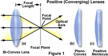
Typical plano-convex lenses (Figure 1(b)) have one positive convex face and a flat (plano) face on the opposite side of the lens. These lens elements focus parallel light rays into a focal point that is positive and forms a real image that can be projected or manipulated by spatial filters. The asymmetry of plano-convex lenses minimizes spherical aberration in applications where the object and image lie at unequal distances from the lens. The optimum case for reduction of aberration occurs when the object is placed at infinity (in effect, parallel light rays enter the lens) and the image is the final focused point. However, the plano-convex lens will produce minimum aberration at conjugate ratios up to approximately 5:1. When the curved surface of a plano-convex lens is oriented toward the object, the sharpest possible focus is achieved. Plano-convex lenses are useful for collimating diverging beams and to apply focus to a more complex optical system.
The positive meniscus lens (Figure 1(c)) has an asymmetric structure with one face shaped as a convex radius, while the opposite face is slightly concave. Meniscus lenses are often employed in conjunction with another lens to produce an optical system having either a longer or shorter focal length than the original lens. As an example, a positive meniscus lens can be positioned after a plano-convex lens to shorten the focal length without decreasing optical system performance. Positive meniscus lenses have a greater curvature radius on the concave side of the lens than on the convex side, enabling formation of a real image.
Contributing Authors
Matthew J. Parry-Hill, Robert T. Sutter and Michael W. Davidson - National High Magnetic Field Laboratory, 1800 East Paul Dirac Dr., The Florida State University, Tallahassee, Florida, 32310.
BACK TO LENSES AND GEOMETRICAL OPTICS