
Interactive Java Tutorials
Interference Between Parallel Light Waves
The classical method of describing interference includes presentations that depict the graphical recombination of two or more sinusoidal light waves in a plot of amplitude, wavelength, and relative phase displacement. In effect, when two waves are added together, the resulting wave has an amplitude value that is either increased through constructive interference, or diminished through destructive interference. This interactive tutorial illustrates the effect by considering a pair of light waves from the same source that are coherent (having an identical phase relationship) and traveling together in parallel.
The tutorial initializes with two parallel light waves, labeled Wave A and Wave B, propagating parallel to each other from left to right in the window. The resultant wave arising from the summation of the two waves by interference is presented as Wave A + B on the right-hand side of the tutorial window. In order to operate the tutorial, use the Wavelength, Phase, and Amplitude sliders to vary these parameters for each of the input waves, and observe how the resultant wave is affected.
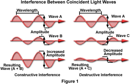
If the vibrations produced by the electric field vectors (which are perpendicular to the propagation direction) from each wave are parallel to each other (in effect, the vectors vibrate in the same plane), then the light waves may combine and undergo interference. If the vectors do not lie in the same plane, and are vibrating at some angle between 90 and 180 degrees with respect to each other, then the waves cannot interfere with one another. The light waves illustrated in Figure 1 are all considered to have electric field vectors vibrating in the plane of the page. In addition, the waves all have the same wavelength, and are coherent, but vary with respect to amplitude. The waves on the right-hand side of Figure 1 have a phase displacement of 180 degrees with respect to each other.
Assuming all of the criteria listed above are met, then the waves can interfere either constructively or destructively to produce a resultant wave that has either increased or decreased amplitude. If the crests of one of the waves coincide with the crests of the other, the amplitudes are determined by the arithmetic sum of the amplitudes from the two original waves. For example, if the amplitudes of both waves are equal, the resultant amplitude would be doubled. In Figure 1, light wave A can interfere constructively with light wave B, because the two coherent waves are in the same phase, differing only in relative amplitudes. Bear in mind that light intensity varies directly as the square of the amplitude. Thus, if the amplitude is doubled, intensity is quadrupled. Such additive interference is called constructive interference and results in a new wave having increased amplitude.
If the crests of one wave coincide with the troughs of the other wave (in effect, the waves are 180-degrees, or half a wavelength, out of phase with each other), the resultant amplitude is decreased or may even be completely canceled, as illustrated for wave A and wave C on the right-hand side of Figure 1. This is termed destructive interference, and generally results in a decrease of amplitude (or intensity). In cases where the amplitudes are equal, but 180-degrees out of phase, the waves eliminate each other producing a total lack of color, or complete blackness. All of the wave examples presented in Figure 1 portray waves propagating in the same direction, but in many cases, light waves traveling in different directions can briefly meet and undergo interference. After the waves have passed each other, however, they will resume their original course, having the same amplitude, wavelength, and phase that they had before meeting.
Real-world interference phenomena are not as clearly defined as the simple case depicted in Figure 1. For example, the large spectrum of color exhibited by a soap bubble results from both constructive and destructive interference of light waves that vary in amplitude, wavelength, and relative phase displacement. Combination of waves having amplitudes that are approximately equal, but with differing wavelengths and phases, can produce a wide spectrum of resultant colors and amplitudes. In addition, when two waves of equal amplitude and wavelength that are 180-degrees (half a wavelength) out of phase with each other meet, they are not actually annihilated, as suggested in Figure 1. All of the photon energy present in these waves must somehow be recovered or redistributed in a new direction, according to the law of energy conservation (photons are not capable of self-annihilation). Instead, upon meeting, the photons are redistributed to regions that permit constructive interference, so the effect should be considered as a redistribution of light waves and photon energy rather than the spontaneous construction or destruction of light. Therefore, simple diagrams, such as the one illustrated in Figure 1, should only be considered as tools that assist with the calculation of light energy traveling in a specific direction.
Contributing Authors
Robert T. Sutter and Michael W. Davidson - National High Magnetic Field Laboratory, 1800 East Paul Dirac Dr., The Florida State University, Tallahassee, Florida, 32310.
BACK TO INTERFERENCE OF LIGHT WAVES