Interactive Tutorials
Adjustment of Digital Image Sharpness
The sharpness of a digital image refers to the degree of clarity in both coarse and fine specimen detail. A lack of sharpness in digital images captured with the microscope often results from poor focus adjustment, vibration, or the specimen not being flat with respect to the imaging plane. This common artifact can also result from a variety of optical aberrations such as spherical aberration, astigmatism, coma, geometrical distortion, and field curvature. Although many of these problems can be corrected by ensuring that the microscope and specimen are properly configured, it is often necessary to correct captured digital images that suffer from a lack of sharpness through digital image processing techniques.
The tutorial initializes with a randomly selected specimen image, captured in the microscope, appearing in the left-hand window entitled Specimen Image. Each specimen name includes, in parentheses, an abbreviation designating the contrast mechanism employed in obtaining the image. The following nomenclature is used: (FL), fluorescence; (BF), brightfield; (DF), darkfield; (PC), phase contrast; (DIC), differential interference contrast (Nomarski); and (POL), polarized light. Visitors will note that specimens captured using the various techniques available in optical microscopy behave differently during image processing in the tutorial.
Adjacent to the Specimen Image window is a Processed Image window, which displays the captured image that has been adjusted for sharpness according to the value specified by the Image Sharpness slider. To operate the tutorial, select an image from the Choose A Specimen pull-down menu, and vary the sharpness level with the Image Sharpness slider. The sharpness setting that is currently selected is displayed above the Image Sharpness slider. Negative values correspond to a reduction in image sharpness, and positive values correspond to an increase in image sharpness.
Many digital cameras contain signal processing circuitry to perform sharpness adjustments after the analog signal has been passed through the analog-to-digital converter. Sharpness adjustments can also be introduced at the software level in a majority of the popular digital image processing programs. In the tutorial, moving the slider to the left introduces a soft blur to the image, while translating the slider past the center position to the right increases sharpness.
The information content of a digital image can be described in terms of the relative spatial frequency of repetitive and isolated image features. High-frequency spatial information in a digital image is characterized by drastic changes in pixel brightness values that occur over a narrow range of pixels, whereas low-frequency spatial information is characterized by gradual changes in pixel brightness values that occur over many pixels. Examples of high-frequency information content include edges and boundaries between features, minute repetitive patterns (such as pores on diatom frustules), as well as many types of noise. Examples of low-frequency information content include regions of the background area or a brightness gradient, which are often characterized by shading that varies gradually throughout the image.
Sharpness reduction involves the removal of high-frequency spatial information from a digital image. This is accomplished by averaging each pixel in the image with its neighboring pixels. The amount of spatial averaging that occurs can be controlled by computing a weighted average of each pixel and its immediate neighbors, or by adjusting the size of the neighborhood that is used to compute the average. When the sharpness slider is moved to the left of the center position in the tutorial, a reduction in sharpness occurs.
A useful algorithm for increasing image sharpness involves subtracting a spatially averaged form of the image from the original. Because the spatially averaged image contains only the low-frequency information obtained from the original image, subtracting the spatially averaged image from the original produces an image that contains only the high-frequency information. Adding this high-frequency image back into the original image results in a sharper image. The degree of sharpening that occurs can be controlled by varying the amount of high-frequency information that is added into the original. When the sharpness slider is moved to the right of the center position in the tutorial, an increase in the sharpness of the image occurs.

Sharpness reduction, or spatial averaging, has the side effect of reducing noise in an image, since many kinds of noise are characterized by high-frequency transitions in pixel brightness values. Increasing image sharpness can raise noise significantly, as the result of enhanced high-frequency information due to the sharpening algorithm. In addition, a reduction in sharpness tends to decrease pixel brightness values, while increasing image sharpening tends to also increase pixel brightness values.
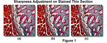
The images presented in Figure 1 demonstrate the effect of sharpness adjustments on a typical specimen collected with a digital microscope. The specimen is an eosin and hematoxylin stained thin section of mammal femur tissue captured in brightfield illumination mode. When sharpness is reduced (Figure 1(a)), fine lines and boundaries that delineate regions of specimen detail are obscured, with a corresponding overall decrease in image brightness. Increasing the sharpness (Figure 1(c)), enhances fine lines and boundaries between regions of specimen detail, revealing detail that is not clearly visible in the original (Figure 1(b)), with an overall increase in image brightness. For reference, the specimen is also illustrated (Figure 1(b)) with no sharpness adjustment.
Contributing Authors
Kenneth R. Spring - Scientific Consultant, Lusby, Maryland, 20657.
John C. Russ - Materials Science and Engineering Department, North Carolina State University, Raleigh, North Carolina, 27695.
Matthew J. Parry-Hill and Michael W. Davidson - National High Magnetic Field Laboratory, 1800 East Paul Dirac Dr., The Florida State University, Tallahassee, Florida, 32310.
BACK TO DIGITAL IMAGE PROCESSING TUTORIALS
