Interactive Tutorials
Digital Image Sampling Frequency
In order to match the optical and electronic resolution of a microscope and the accompanying camera system, a digital image should have a sufficient number of samples per horizontal line so that the display faithfully represents the original signal presented to the digitizing device. This interactive tutorial explores how variations in specimen sampling frequency affect the resolution of the final image.
The tutorial initializes with a randomly generated analog signal appearing in the window entitled Signal Sampling Frequency. Beneath the window is a Sampling Frequency slider that enables the user to vary the frequency within a range of one sample for every pixel to one sample for each 32 pixels. The tutorial can be reset to a new analog signal by depressing the Reset button with the mouse cursor.
When an analog signal is digitized at an inadequate sampling frequency (in effect, when the Sampling Frequency slider is adjusted to values exceeding a few pixels per sample), events are missed and a phenomenon known as aliasing develops. Aliasing can result not only in the loss of important high-spatial-frequency information but also in the introduction of spurious lower-frequency data, as discussed in more detail below.
The spatial resolution of a digital image is determined by the distance between pixels, known as the sampling interval, and the accuracy of the digitizing device. The numerical value of each pixel in the digital image represents the intensity of the optical image averaged over the sampling interval. Optical image features that are smaller than the digital sampling interval will not be represented accurately in the digital image. It is important to note that there are other real-world considerations involved in image resolution that complicate the concept of a simple relationship between sampling interval at the imaging device (such as a CCD) and the corresponding interval in the specimen. While it is useful to know the interval at which the imaging device is capable of sampling in a theoretical sense, most capture devices do not sample at discrete points, but integrate over a significant area. For this and other reasons, it is difficult in practice to directly relate the size of features observed in the optical image to an "effective" sampling interval that is necessary in the digitizer to preserve the features. In spite of this practical complication, the tutorial demonstrates the relationship between sampling frequency and image resolution.
According to Shannon's sampling theorem, in order to preserve the spatial resolution of the original image, the digitizing device must utilize a sampling interval that is no greater than one-half the size of the smallest resolvable feature of the optical image. This is equivalent to acquiring samples at twice the highest spatial frequency contained in the image, a reference point commonly referred to as the Nyquist criterion. If the Abbe limit of resolution in the optical image is approximately 0.22 micrometers, the digitizer must sample at intervals that correspond in the specimen space to 0.11 micrometers or less. A digitizer that samples 512 points per horizontal scan line would then have a maximum horizontal field of view of approximately 56 micrometers (512 x 0.11 micrometers). An increased number of digital samples per scan line or unit specimen area, which could be brought about by too great an optical magnification, would not yield more spatial information and the image would be said to be oversampled. Note that oversampling is often done intentionally to examine or display diffraction patterns or point spread functions, to produce a reduced field of view, or to acquire redundant values to ensure fidelity of the displayed image. In most cases, to ensure adequate sampling for high-resolution imaging, an interval of 2.5 to 3 samples for the smallest resolvable feature is desirable.

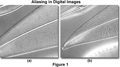
In cases where pixels generated by the digitizer are spaced too far apart compared to the high-frequency detail of the image, this specimen information may then masquerade as lower spatial frequency image features that are not actually present in the specimen. Aliasing is a peculiar phenomenon that occurs abruptly when the sampling frequency drops below a critical level and can result in the generation of moiré patterns in specimens with regularly spaced, repetitive patterns, such as those seen in the diatoms illustrated in Figure 1. In this figure, the left panel (a) displays an image of a diatom obtained with a 40x objective having a numerical aperture of 0.90 and a 1.5x auxiliary lens. The right panel (b) shows the same viewfield without the auxiliary lens. Aliasing is present in panel (b) and appears as a series of low-frequency bars on the diatom frustule. In most cases aliasing suddenly develops at a sampling frequency less than or equal to about 1.5 times that of the repetitive, high-frequency pattern, as observed in the figure. It should be noted that while the spatial frequency of the resultant image is artifactually altered by aliasing, the amplitude of the signal is not significantly changed.
Contributing Authors
Kenneth R. Spring - Scientific Consultant, Lusby, Maryland, 20657.
John C. Russ - Materials Science and Engineering Department, North Carolina State University, Raleigh, North Carolina, 27695.
Matthew J. Parry-Hill, Thomas J. Fellers, Laurence D. Zuckerman, and Michael W. Davidson - National High Magnetic Field Laboratory, 1800 East Paul Dirac Dr., The Florida State University, Tallahassee, Florida, 32310.
BACK TO DIGITAL IMAGE PROCESSING TUTORIALS
