Differential Interference Contrast
Interactive Tutorials
Optical Staining with DIC Microscopy
By introducing birefringent compensator plates into the optical pathway of a differential interference contrast (DIC) microscope, transparent specimens that are otherwise rendered over a limited range of grayscale values can be transformed to display a wide array of colors through the technique known as optical staining. This interactive tutorial explores how varying the amount of bias retardation can affect the appearance and level of staining achieved in the specimen image.
The tutorial initializes with a randomly selected DIC image appearing in the Specimen Image window having a small bias retardation value (one-twentieth of a wavelength) applied to the optical system. To operate the tutorial, translate the Bias Retardation slider to higher values (to the right) in order to produce higher-order interference colors in the specimen image. This slider has an operational range between 1/20 and a full wavelength of retardation. New specimens can be examined by selecting the appropriate choice in the Choose A Specimen pull-down menu.
Bias retardation between the ordinary and extraordinary wavefronts in differential interference contrast can be manipulated through the use of compensators originally targeted as quantitative retardation measuring devices and contrast-enhancing elements for polarized light microscopy. Compensating plates bestow greater control for adjusting the contrast of specimen details in relation to the background intensity and color values, and also enable more precise tuning of the bias value between wavefronts. These birefringent components are also frequently employed for optical staining of transparent specimens, which are normally rendered over a limited range of grayscale values.
When a standard objective Nomarski prism is translated along the microscope optical axis beyond path differences of one-quarter wavelength, both specimen features and the background acquire a spectrum of Newtonian interference colors similar to those observed in polarized light microscopy. The specimen and background become optically stained with a transition of color that migrates through a series of gray values through white, yellow, red-blue and higher orders. Optical staining produces dramatic and beautifully colored images, but has limited use for scientific applications. Usually, the optimum specimen contrast is limited to the range of one-twentieth to one-quarter wavelength of retardation.
Compensators can be inserted into the optical pathway of a DIC microscope between either the objective prism and the analyzer or the polarizer and the condenser prism. Many microscopes have a slot located in the intermediate tube or substage condenser housing designed for this purpose. Addition of a first-order compensator (often termed a full-wave or first-order red plate) having a retardation value equal to a full wavelength in the green region of visible light (approximately 550 nanometers), introduces a spectrum of interference colors to the specimen and background. With the compensator in place, green light is unable to pass through the analyzer because it emerges from the retardation plate linearly polarized with an electric field vector having the same orientation as the polarizer. However, wavefronts in the red and blue spectral regions experience retardations less than a wavelength and become elliptically polarized, allowing them to pass a component through the analyzer. As a result, these colors become mixed to form a magenta background in the field of view.

Thus, when a specimen is observed in white light with differential interference contrast optics and a first-order compensator, the background appears magenta while image contrast is displayed in the second-order blue and first-order yellow colors (depending on orientation) of the Newtonian interference color spectrum. With the compensator in place, small variations in bias retardation obtained by translation of the Nomarski prism (or rotating the polarizer in a de Sénarmont compensator) yield rapid changes to interference colors observed in structures having large path length gradients. This technique is useful for introducing color (optical staining) to regions having high refractive index boundaries, such as cellular membranes, large intracellular particles, cilia, and the nucleus. The interference colors displayed by specimen features can be compared to the values on a Michel-Levy color chart to obtain an estimate of the optical path difference.
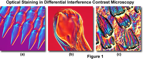
Illustrated in Figure 1 are several transparent specimens that have been optically stained and rendered in pseudo three-dimensional relief through DIC optical techniques. Figure 1(a) depicts projections at the edge of a ctenoid fish scale, while the mouth of a canine hookworm (Ancylostoma caninum) is featured in Figure 1(b). Colorful wing scales of the Great Leopard moth (Ecpantheria scribonia) are presented in Figure 1(c). In all cases, the Nomarski prism was translated across the microscope optical axis to a bias retardation value exceeding a full wavelength. Although these images do not reveal hidden scientific information pertaining to the specimens, they do have the potential to advance the technique of DIC optical microscopy as a legitimate bridge between science and art.
On microscopes equipped with a de Sénarmont compensator for introducing bias into a differential interference contrast optical system, a full-wave retardation plate can be added to optically stain the specimen with Newtonian interference colors and provide more quantitative information about path differences. The de Sénarmont compensator is frequently employed in DIC microscopy to obtain precisely measured levels of bias retardation, but the device is also useful to monitor alignment of the optical components. In video-enhanced DIC (VE-DIC) microscopy, de Sénarmont compensators are often utilized to optimize contrast in specimen detail that lies below the resolution limit of the microscope.
Contributing Authors
Douglas B. Murphy - Department of Cell Biology and Microscope Facility, Johns Hopkins University School of Medicine, 725 N. Wolfe Street, 107 WBSB, Baltimore, Maryland 21205.
Jan Hinsch - Leica Microsystems, Inc., 90 Boroline Road, Allendale, New Jersey, 07401.
Kenneth R. Spring - Scientific Consultant, Lusby, Maryland, 20657.
Matthew J. Parry-Hill and Michael W. Davidson - National High Magnetic Field Laboratory, 1800 East Paul Dirac Dr., The Florida State University, Tallahassee, Florida, 32310.
BACK TO DIFFERENTIAL INTERFERENCE CONTRAST MICROSCOPY
