Differential Interference Contrast
Interactive Tutorials
de Sénarmont Compensators
A de Sénarmont compensator is composed of a linear polarizer combined with a quarter-wavelength retardation plate, and is capable of producing either linear, elliptical, or circularly polarized light, depending upon the orientation of the polarizer vibration axis with respect to the fast and slow axes of the retardation plate. This interactive tutorial explores the relationship between wavefronts emanating from the compensator as the polarizer is rotated through its useful range.
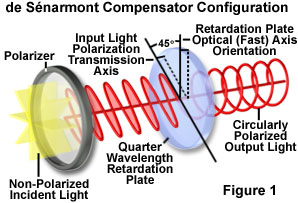
The tutorial initializes with a beam of non-polarized white light impacting the polarizer from the left-hand side of the window. After passing through the polarizer (the gray disc), which has a transmission axis indicated by a long black wedge, the emerging linearly polarized light is oriented with the vibration direction oriented parallel to the fast axis of the quarter-wavelength retardation plate (represented by a black wedge on the light blue disc). In this configuration, the de Sénarmont compensator passes linearly polarized light, which is represented in the tutorial by a blue sine wave accompanied by an oscillating black arrow that traces the electric vector vibration orientation. When linear polarized light passes through the compensator, the retardation value is zero, as indicated in the yellow box positioned near the upper left-hand corner of the tutorial window. The entire compensator assembly can be rotated within the window by placing the mouse cursor on any component, and then dragging to model to a new position. For reference purposes, a schematic drawing is presented in Figure 1 that outlines the basic de Sénarmont compensator configuration motif for the input of linearly polarized light oriented at a 45-degree angle to the retardation plate fast axis.
The orientation of incident linearly polarized light with respect to the retardation (quarter-wavelength) plate can be altered by translating the Polarizer Rotation slider to either the right or left from its default central position. When the slider is moved to the left (negative values), between a range of 1 and 44 degrees, an increasing amount of light is passed through the slow axis of the retardation plate (indicated by a red sine wave exiting red wedges on the blue disc). The net result is the production of right-handed elliptically polarized light. The opposite effect occurs when the slider is moved to the right (positive values; left-handed elliptically polarized light). Elliptically polarized light is represented in the tutorial by a three-dimensional trajectory of the black arrow, which traces the vector sum of the individual electronic components from each wave (fast and slow).

When the Polarizer Rotation slider is moved either to the -45 or +45 degree position, light waves traveling through the fast and slow axes of the retardation plate have equal amplitudes (but with one wave retarded by 45 degrees), and the light emerging from the retardation plate is circularly polarized. In this case, the pathway scribed by the vector sum black arrow is circular. These effects are observed more clearly when the compensator is dragged to the front of the window and the waves are viewed end-on. As the Polarizer Rotation slider is translated, the retardation value of the complete de Sénarmont compensator is constantly updated and presented in the yellow box (near the upper left-hand corner of the tutorial).
The Fast and Slow radio buttons can be utilized to reverse the axes of the retardation plate (also reversing the handedness of the elliptically and circularly polarized light). Translation of the sine wave(s) can be halted by removing the check mark in the Translate Sine Wave checkbox. The Applet Speed slider controls the speed of the sine wave(s), while the Pause button will freeze the applet in the current configuration, but still enable rotation of the model through all three dimensions. Clicking the Reset button will return the tutorial to its initialization state.
Bias has been traditionally introduced into the differential interference contrast microscope by translating the objective Nomarski prism back and forth along the optical axis using a fine adjustment knob located at the end of the mounting frame (usually positioned in the microscope nosepiece housing or an intermediate tube). An alternative technique, which is growing in popularity, is to mount a quarter-wavelength retardation plate in fixed orientation between the polarizer and condenser prism (termed de Sénarmont DIC compensation, as described above). At maximum extinction, the fast axis of the retardation plate is aligned with the transmission axis of the polarizer, and both optical units can be (and often are) contained within the same housing on the base of the microscope. An alternative location for the de Sénarmont compensator, in microscopes equipped with the appropriate intermediate tube, is between the objective prism and the analyzer.
In order to introduce bias using the de Sénarmont compensator, the polarizer transmission axis is rotated (up to 45 degrees) with respect to the fast axis of the compensator, which remains fixed at a 90-degree angle relative to the analyzer transmission axis. When the compensator fast axis coincides (is parallel) with the transmission axis of the polarizer, only linearly polarized light passes through the de Sénarmont compensator to the condenser prism. However, when the polarizer transmission axis is rotated, wavefronts emerging from the compensator plate become elliptically polarized. Rotating the polarizer in one direction will produce right-handed elliptically polarized light, while rotating the polarizer in the other direction will alter the vector trajectory to generate a left-handed elliptical sweep.

When the orientation of the polarizer transmission axis reaches either plus or minus 45 degrees (equivalent to one-quarter wavelength retardation), light passing through the compensator becomes circularly polarized (again in either a left-handed or right-handed sense). Because elliptically or circularly polarized light represents a phase difference between the ordinary and extraordinary wavefronts emerging from the de Sénarmont compensator, bias is introduced to the system when the wavefronts enter the condenser prism and become sheared. Positive bias is obtained when the polarizer is rotated in one direction, while negative bias is introduced by rotating the polarizer in the opposite direction.
Regardless of whether bias is introduced into a differential interference contrast system by translating the objective Nomarski prism or by rotating the polarizer on a de Sénarmont compensator, the net result is the same. In a properly configured microscope that is aligned for Köhler illumination, an image of the light source and condenser prism is transferred by the optical system (condenser and objective) onto the inverted second Nomarski prism located at the objective rear focal plane. The linear phase shift across the face of the condenser prism is precisely compensated by an opposite phase shift in the objective prism. Translation of the objective prism along the shear axis does not alter the phase shift distribution, but instead, adds or subtracts a constant phase difference across the entire microscope aperture. In the same manner, rotating the polarizer in a de Sénarmont compensator also introduces a variable and controlled phase difference. The matched prism system enables image formation to occur with the same bias retardation for every wavefront pair projected from the condenser aperture, irrespective of the route through which it traverses the specimen to reach the objective.
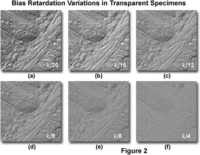
Presented in Figure 2 is a series of digital images recorded in DIC using a bias retardation range of one-twentieth to a quarter wavelength in several intermediate steps. The specimen is a 15-micrometer section of fixed and mounted murine intestine that contains regions of fluctuating thickness. Rendition of specimen detail and the shadow-cast pseudo three-dimensional effects are the most pronounced at the lower bias retardation values (Figures 2(a) and 2(b)), and both contrast and definition of fine specimen detail deteriorate as bias retardation is increased (Figures 2(c) through 2(f)). At the highest bias retardation value (one-quarter wavelength; Figure 2(f)), contrast is extremely poor and very few structural details are visible. For this particular specimen, the optimum retardation range appears to lie between one-twentieth and one-twelfth of a wavelength.
As the optical path gradient in a specimen increases, so does image contrast. Altering the bias retardation to varying degrees can also produce significant contrast fluctuations in the specimen as observed in the eyepieces (Figure 2). In general, the optimum degree of displacement between the ordinary and extraordinary wavefronts induced by translation of the objective prism or by rotating the polarizer in a de Sénarmont compensator is on the order of less than one-tenth wavelength. However, this value is largely dependent on specimen thickness, and the useful range of bias retardation for biological specimens lies between one-thirtieth and a quarter wavelength. Contrast in specimens having very large optical gradients can often benefit from even greater bias retardation values (up to a full wavelength). The introduction of bias retardation into a differential interference contrast microscope enables phase specimens to be observed with greater ease, and dramatically facilitates imaging efforts with traditional film or digital camera systems.
Contributing Authors Jan Hinsch - Leica Microsystems, Inc., 110 Commerce Drive, Allendale, New Jersey, 07401. Matthew J. Parry-Hill and Michael W. Davidson - National High Magnetic Field Laboratory, 1800 East Paul Dirac Dr., The Florida State University, Tallahassee, Florida, 32310.
BACK TO DIFFERENTIAL INTERFERENCE CONTRAST MICROSCOPY
