Concepts in Digital Imaging Technology
Dynamic Range
The dynamic range of a charge-coupled device (CCD) or complementary metal oxide semiconductor (CMOS) image sensor is typically specified as the maximum achievable signal divided by the camera noise, where the signal strength is determined by the full-well capacity, and noise is the sum of dark and read noises. As the dynamic range of a device is increased, the ability to quantitatively measure the dimmest intensities in an image (intrascene performance) is improved. The interscene dynamic range represents the spectrum of intensities that can be accommodated when detector gain, integration time, lens aperture, and other variables are adjusted for differing fields of view.

Photodiode size determines, in part, the size of the depletion wells--larger diodes having greater full-well capacity compared to camera noise. Typical diode sizes in modern CCDs utilized in photomicrography range from 4.5 to 24 microns with corresponding well capacities of 20,000 to 600,000 electrons. Read noise is a combination of all noise generated during readout of the device. This includes noise from input clocking and fixed pattern, along with reset transistor noise and amplifier output noise. Read noise is usually specified in the performance data sheets that accompany a CCD sensor, with typical values ranging from 10-20 electrons/pixel in high quality chips operated at room temperature, and dropping to 2-5 electrons/pixel in Peltier-cooled CCDs for scientific imaging applications. The dynamic range is expressed in decibel units according to the following equation:
where N(sat) is the linear full well capacity stated as the number of electrons and N(noise) is the total value of the read and dark noise, also expressed as the number of electrons. In a high-performance cooled CCD camera, the well capacity is proportional to the size of the individual photodiode, such that the maximum number of electrons stored is about 1000 times the cross sectional area of each photodiode. Thus, a CCD with 6.7 x 6.7 micron photodiodes should have a maximum charge storage capacity (a full-well capacity) of about 44,900 electrons (or holes). At a typical readout rate of 1 MHz, the read noise for this CCD is about 10 electrons/pixel, which yields a dynamic range of 44,900/10 or 4,490. In order to utilize the full range of grayscale levels available with this dynamic range, the camera should have a 12-bit analog-to-digital (A/D) converter capable of resolving 4096 gray levels. Controlling the size of the read and dark noise is a critical factor in maintaining a high dynamic range in these devices.
Higher performance cooled CCD sensors designed with low noise output amplifiers and suitable for use in slow-scan imaging of photomicrographs often have lower read noise and an extended dynamic range. As an example, the Marconi Applied Technologies CCD39-01 sensor is a back-illuminated, frame-transfer CCD having a square pixel size of 24 microns with a split output register allowing the utilization of quad output amplifiers. The full well capacity of this device can reach a level 300,000 electrons. Coupled with a readout noise root-mean-square (rms) level of three electrons at 20 kilohertz (when cooled), the CCD39-01 is capable of yielding a dynamic range of approximately 100,000:1. To fully utilize the potential of this CCD, a 17-bit A/D converter having 131,072 grayscale levels should be employed (although a 16-bit A/D converter having 65,536 grayscale levels would also suffice).
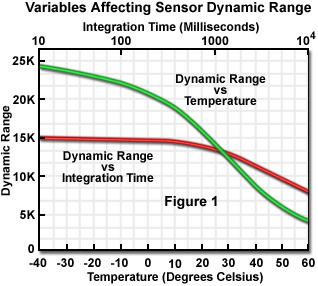
The dynamic range of a particular CCD is dependent upon several variables. Dark current is strongly influenced by temperature (Figure 1), doubling every 8 to 10 degrees Centigrade. At higher temperatures, dark current is dominant, while at lower temperatures, dynamic range is determined by the noise of the output amplifier. The amount of dark charge collected in each pixel is dependent not only on the device temperature, but also on the integration time and the storage time before readout. The noise level is also proportional to the bandwidth of the read-out amplifier, which is influenced by pixel transfer rate and is thus affected by the clock frequency. As the clocking frequency is increased, the number of dark current and shot noise electrons is correspondingly decreased and less bandwidth is required by the output amplifier and video-processing electronics. Integration time also affects the dynamic range of a CCD, as illustrated in Figure 1. An increase in the total integration time produces an increase in dark current and a subsequent decrease in dynamic range, but this effect only comes into play at integration times exceeding 5 minutes.

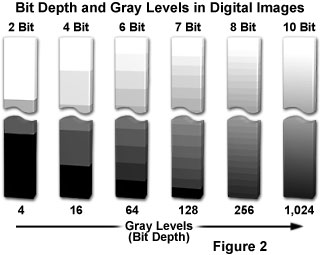
Bit depth refers to the binary range of possible grayscale values utilized by the A/D converter to translate analog image information into discrete digital values capable of being read and analyzed by a computer. For example, the most popular 8-bit A/D converters have a binary range of 2•(E8) or 256 possible values (Figure 2), while a 12-bit converter has a range of 2•(E12) or 4,096 values, and a 16-bit converter has 2•(E16), or 65,536 possible values. The bit depth of the A/D converter determines the size of the gray scale increments, with higher bit depths corresponding to a greater range of useful image information available from the camera. Better results are obtained when the signal is sampled at a level that is well beneath the limit suggested by the readout noise. For instance, if the Marconi CCD39-01 is used with signal averaging, an 18-bit (262,144 grayscale levels) A/D converter might be used to sample data at 1 part in 262,144. However, the noise level statistics for this device indicate that image data cannot be accurately measured to greater than 1 part in 100,000 without signal averaging. Clearly, a 16-bit or 18-bit A/D converter will produce better results when coupled to the Marconi CCD39-01 chip. In contrast, Fujichrome Velvia, a fine-grained color transparency film, has been demonstrated to produce less than 10-stops (1024 grayscale levels) of dynamic range.
Table 1 presents the relationship between the number of bits used to store digital information, the numerical equivalent in grayscale levels, and the corresponding value in decibels (one bit equals approximately 6 dB). As illustrated in the table, if a 0.72 volt video signal were digitized by an A/D converter with 1-bit accuracy, the signal would be represented by two values, binary 0 or 1 with voltage values of 0 and 0.72 volts. Most digitizers found in digital cameras used in photomicrography employ 8 bit A/D converters, which have 256 discrete grayscale levels (between 0 and 255), to represent the voltage amplitudes. A maximum signal of 0.72 volts would then be subdivided into 256 steps, each step having a value of 2.9 millivolts.
Bit Depth and Dynamic Range of Charge-Coupled Devices
|
||||||||||||||||||||||||||||||||||||||||||||||||||||||||
Table 1
The number of grayscale levels that must be generated in order to achieve acceptable visual quality should be enough that the steps between individual gray values are not discernible to the human eye. The "just noticeable difference" in intensity of a gray-level image for the average human eye is about two percent under ideal viewing conditions. At most, the eye can distinguish about 50 discrete shades of gray within the intensity range of a video monitor, suggesting that the minimum dynamic range of an image should lie between 6 and 7 bits (64 and 128 grayscale levels; Figure 2).
Digital images should have at least 8-bit resolution to avoid producing visually obvious gray-level steps in the enhanced image when contrast is increased during image processing. The effect of reducing the number of grayscale levels on the appearance of photomicrographs can be seen in Figure 3, which shows a black & white (originally 8-bit) image of stained thin section of Solanum tuberosum (potato) that is displayed at different resolutions ranging from 6-bit (Figure 3(a)), down to 5-bit (Figure 3(b)), 4-bit (Figure 3(c)), and 3-bit (Figure 3(d)).

Improved digital cameras with CCDs capable of 12-bit resolution allow investigators to display images with a greater latitude than is possible with 8-bit images. This is possible because the appropriate software can render the necessary shades of gray from a larger palette (4,096 grayscale levels) for display on computer monitors, which typically present images in 256 shades of gray. In contrast, an 8-bit digital image is restricted to a palette of 256 grayscale levels that were originally captured by the digital camera. As the magnification is increased during image processing, the software can choose the most accurate grayscales to reproduce portions of the enlarged image without changing the original data. This is especially important when examining shadowed areas where the depth of the 12-bit digital image allows the investigator to visualize subtle details that would not be present in an 8-bit image.
The accuracy required for digital conversion of analog video signals is dependent upon the difference between a digital gray-level step and the rms noise in the camera output. CCD cameras with an internal A/D converter produce a digital data stream that does not need to be resampled and digitized in the computer. These cameras are capable of producing digital data with up to 18-bit resolution (262,144 grayscales) in high-end models, and are not constrained to the 0.72-volt signal limitation of RS-170 video systems and utilize a wider analog voltage range in their A/D converters. The major advantage of the large digital range exhibited by CCD cameras lies in the signal-to-noise improvements in the displayed 8-bit image and in the wide linear dynamic range over which signals can be digitized.
Contributing Authors
Kenneth R. Spring - Scientific Consultant, Lusby, Maryland, 20657.
Michael W. Davidson - National High Magnetic Field Laboratory, 1800 East Paul Dirac Dr., The Florida State University, Tallahassee, Florida, 32310.
BACK TO CONCEPTS IN DIGITAL IMAGING TECHNOLOGY
