Reflected Light Microscopy
Introduction
Reflected light microscopy is often referred to as incident light, epi-illumination, or metallurgical microscopy, and is the method of choice for fluorescence and for imaging specimens that remain opaque even when ground to a thickness of 30 microns.
The range of specimens falling into this category is enormous and includes most metals, ores, ceramics, many polymers, semiconductors (unprocessed silicon, wafers, and integrated circuits), slag, coal, plastics, paint, paper, wood, leather, glass inclusions, and a wide variety of specialized materials. Because light is unable to pass through these specimens, it must be directed onto the surface and eventually returned to the microscope objective by either specular or diffused reflection. As mentioned above, such illumination is most often referred to as episcopic illumination, epi-illumination, or vertical illumination (essentially originating from above), in contrast to diascopic (transmitted) illumination that passes through a specimen.
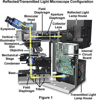
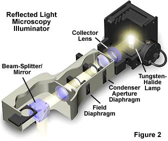
Today, many microscope manufacturers offer models that permit the user to alternate or simultaneously conduct investigations using both vertical and transmitted illumination. A typical microscope configured for both types of illumination is illustrated in Figure 1. The optical pathway for reflected light begins with illuminating rays originating in the lamp housing for reflected light (the upper housing in Figure 1 and Figure 3). This light next passes through the collector lens and into the vertical illuminator (Figure 2) where it is controlled by the aperture and field diaphragms. After passing through the vertical illuminator, the light is then reflected by a beamsplitter (a half mirror or elliptically shaped first-surface mirror) through the objective to illuminate the specimen.
Light reflected from the surface of the specimen re-enters the objective and passes into the binocular head where it is directed either to the eyepieces or to a port for photomicrography. Reflected light microscopy is frequently the domain of industrial microscopy, especially in the rapidly growing semiconductor arena, and thus represents a most important segment of microscopical studies.
| Interactive Tutorial | |||||||||||
|
|||||||||||
A typical upright compound reflected light microscope also equipped for transmitted light has two eyepiece viewing tubes (Figure 1) and often a trinocular tube head for mounting a conventional or digital/video camera system (not illustrated). Standard equipment eyepieces are usually of 10x magnification, and most microscopes are equipped with a nosepiece capable of holding four to six objectives. The stage is mechanically controlled with a specimen holder that can be translated in the X- and Y- directions and the entire stage unit is capable of precise up and down movement with a coarse and fine focusing mechanism.
Built-in light sources range from 20 and 100 watt tungsten-halogen bulbs to higher energy mercury vapor or xenon lamps that are used in fluorescence microscopy. Light passes from the lamphouse through a vertical illuminator interposed above the nosepiece but below the underside of the viewing tube head. The specimen's top surface is upright (usually without a coverslip) on the stage facing the objective, which has been rotated into the microscope's optical axis. The vertical illuminator is horizontally oriented at a 90-degree angle to the optical axis of the microscope and parallel to the table top, with the lamp housing attached to the back of the illuminator. The coarse and fine adjustment knobs raise or lower the stage in large or small increments to bring the specimen into sharp focus.
Another variation of the reflected light microscope is the inverted microscope—of the Le Chatelier design (Figure 4). On the inverted stand, the specimen is placed on the stage with its surface of interest facing downward. The primary advantage of this design is that samples can be easily examined when they are far too large to fit into the confines of an upright microscope. Also, only the side facing the objectives need be perfectly flat. The objectives are mounted on a nosepiece under the stage with their front lenses facing upward towards the specimen and focusing is accomplished either by moving the nosepiece or the entire stage up and down.
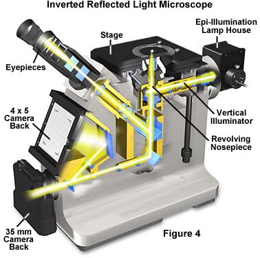
Inverted microscope stands incorporate the vertical illuminator within the body of the microscope. Many types of objectives can be used with inverted reflected light microscopes, and all modes of reflected light illumination may be possible: brightfield, darkfield, polarized light, differential interference contrast, and fluorescence. Many of the inverted microscopes have built-in 35 millimeter and/or large format cameras or are modular to allow such accessories to be attached. Some of the instruments include a magnification changer for zooming in on the image, contrast filters, and a variety of reticles. Because an inverted microscope is a favorite instrument for metallographers, it is often referred to as a metallograph. Manufacturers are largely migrating to using infinity-corrected optics in reflected light microscopes, but there are still thousands of fixed tube length microscopes in use with objectives corrected for a tube length between 160 and 210 millimeters.
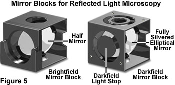
In the vertical illuminator, light travels from the light source, usually a 12 volt 50 or 100 watt tungsten halogen lamp, passes through collector lenses, through the variable aperture iris diaphragm opening and through the opening of a variable and centerable pre-focused field iris diaphragm. The light then strikes a partially silvered plane glass reflector, or strikes a fully silvered periphery of a mirror with elliptical opening for darkfield illumination (Figure 5). The plane glass reflector is partially silvered on the glass side facing the light source and anti-reflection coated on the glass side facing the observation tube in brightfield reflected illumination. Light is thus deflected downward into the objective. The mirrors are tilted at an angle of 45 degrees to the path of the light travelling along the vertical illuminator.
The light reaches the specimen, which may absorb some of the light and reflect some of the light, either in a specular or diffuse manner. Light that is returned upward can be captured by the objective in accordance with the objective's numerical aperture and then passes through the partially silvered mirror (or in darkfield, through the elliptical opening). In the case of infinity-corrected objectives, the light emerges from the objective in parallel (from every azimuth) rays projecting an image of the specimen to infinity. The parallel rays enter the tube lens, which forms the specimen image at the plane of the fixed diaphragm opening in the eyepiece (intermediate image plane). It is important to note, that in these reflected light systems, the objective serves a dual function: on the way down as a matching well-corrected condenser properly aligned; on the way up as an image-forming objective in the customary role of an objective projecting the image-carrying rays toward the eyepiece. Optimal performance is achieved in reflected light illumination when the instrument is adjusted to produce Köhler illumination. A function of Köhler illumination (aside from providing evenly dispersed illumination) is to ensure that the objective will be able to deliver excellent resolution and good contrast even if the source of light is a coil filament lamp.
Some modern reflected light illuminators are described as universal illuminators because, with several additional accessories and little or no dismantling, the microscope can easily be switched from one mode of reflected light microscopy to another. Often, reflectors can be removed from the light path altogether in order to permit transmitted light observation. Such universal illuminators may include a partially reflecting plane glass surface (the half-mirror) for brightfield, and a fully silvered reflecting surface with an elliptical, centrally located clear opening for darkfield observation. The best-designed vertical illuminators include collector lenses to gather and control the light, an aperture iris diaphragm and a pre-focused, centerable field diaphragm to permit the desirable Köhler illumination.
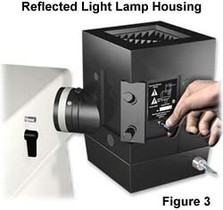
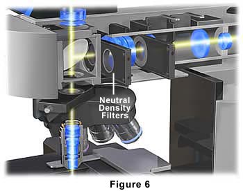
The vertical illuminator (Figure 2) should also make provision for the insertion of filters for contrast and photomicrography, polarizers, analyzers, and compensator plates for polarized light and differential interference contrast illumination. In vertical illuminators designed for with infinity-corrected objectives, the illuminator may also include a tube lens. Affixed to the back end of the vertical illuminator is a lamphouse (Figure 3), which usually contains a tungsten-halogen lamp. For fluorescence work, the lamphouse can be replaced with a fitting containing a mercury burner. The lamp may be powered by the electronics built into the microscope stand, or in fluorescence, by means of an external transformer or power supply.
In reflected light microscopy, absorption and diffraction of the incident light rays by the specimen often lead to readily discernible variations in the image, from black through various shades of gray, or color if the specimen is colored. Such specimens are known as amplitude specimens and may not require special contrast methods or treatment to make their details visible. Other specimens show so little difference in intensity and/or color that their feature details are extremely difficult to discern and distinguish in brightfield reflected light microscopy. Such specimens behave much like the phase specimens so familiar in transmitted light work, and are suited for darkfield and reflected light differential interference contrast applications.
Contributing Authors
Mortimer Abramowitz - Olympus America, Inc., Two Corporate Center Drive., Melville, New York, 11747.
Michael W. Davidson - National High Magnetic Field Laboratory, 1800 East Paul Dirac Dr., The Florida State University, Tallahassee, Florida, 32310.
BACK TO ANATOMY OF THE MICROSCOPE
