
Eyepieces (Oculars)
Eyepieces work in combination with microscope objectives to further magnify the intermediate image so that specimen details can be observed. Oculars is an alternative name for eyepieces that has been widely used in the literature, but to maintain consistency during this discussion we will refer to all oculars as eyepieces.
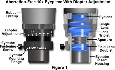
Best results in microscopy require that objectives be used in combination with eyepieces that are appropriate to the correction and type of objective. The basic anatomy of a typical modern eyepiece is illustrated in Figure 1. Inscriptions on the side of the eyepiece describe its particular characteristics and function.
The eyepieces illustrated in Figure 1 are inscribed with UW, which is an abbreviation for the Ultra Wide viewfield. Often eyepieces will also have an H designation, depending upon the manufacturer, to indicate a high eye point focal plane that allows microscopists to wear glasses while viewing samples. Other inscriptions often found on eyepieces include WF for Wide-Field; UWF for Ultra Wide-Field; SW and SWF for Super Wide-Field; HE for High Eye point; and CF for eyepieces intended for use with CF corrected objectives. Compensating eyepieces are often inscribed with K, C, or comp as well as the magnification. Eyepieces used with flat-field objectives are sometimes labeled Plan-Comp. The eyepiece magnification of the eyepieces in Figure 1 is 10x (indicated on the housing), and the inscription A/24 indicates the field number is 24, which refers to the diameter (in millimeters) of the fixed diaphragm in the eyepiece. These eyepieces also have a focus adjustment and a thumbscrew that allows their position to be fixed. Manufactures now often produce eyepieces having rubber eye-cups that serve both to position the eyes the proper distance from the front lens, and to block room light from reflecting off the lens surface and interfering with the view.
There are two major types of eyepieces that are grouped according to lens and diaphragm arrangement: the negative eyepieces with an internal diaphragm and positive eyepieces that have a diaphragm below the lenses of the eyepiece. Negative eyepieces have two lenses: the upper lens, which is closest to the observer's eye, is called the eye-lens and the lower lens (beneath the diaphragm) is often termed the field lens. In their simplest form, both lenses are plano-convex, with convex sides "facing" the specimen. Approximately mid-way between these lenses there is a fixed circular opening or internal diaphragm which, by its size, defines the circular field of view that is observed in looking into the microscope.
The simplest negative eyepiece design, often termed the Huygenian eye-piece (illustrated in Figure 2), is found on most teaching and laboratory microscopes fitted with achromatic objectives. Although the Huygenian eye and field lenses are not well corrected, their aberrations tend to cancel each other out. More highly corrected negative eyepieces have two or three lens elements cemented and combined together to make the eye lens. If an unknown eyepiece carries only the magnification inscribed on the housing, it is most likely to be a Huygenian eyepiece, best suited for use with achromatic objectives of 5x-40x magnification.
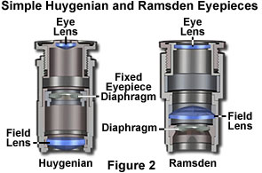
The other main kind of eyepiece is the positive eyepiece with a diaphragm below its lenses, commonly known as the Ramsden eyepiece, as illustrated in Figure 2 (on the left). This eyepiece has an eye lens and field lens that are also plano-convex, but the field lens is mounted with the curved surface facing towards the eye lens. The front focal plane of this eyepiece lies just below the field lens, at the level of the eyepiece diaphragm, making this eyepiece readily adaptable for mounting reticles. To provide better correction, the two lenses of the Ramsden eyepiece may be cemented together.
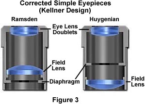
A modified version of the Ramsden eyepiece is known as the Kellner eyepiece, as illustrated on the left in Figure 3. These improved eyepieces contain a doublet of eye-lens elements cemented together and feature a higher eye point than either the Ramsden or Huygenian eyepiece as well as a much larger field of view. A modified version of the simple Huygenian eyepiece is also illustrated in Figure 3, on the right. While these modified eyepieces perform better than their simple one-lens counterparts, they are still only useful with low-power achromat objectives.
Simple eyepieces such as the Huygenian and Ramsden and their achromatized counterparts will not correct for residual chromatic difference of magnification in the intermediate image, especially when used in combination with high magnification achromatic objectives as well as any fluorite or apochromatic objectives. To remedy this, manufacturers produce compensating eyepieces that introduce an equal, but opposite, chromatic error in the lens elements. Compensating eyepieces may be either of the positive or negative type, and must be used at all magnifications with fluorite, apochromatic and all variations of plan objectives (they can also be used to advantage with achromatic objectives of 40x and higher). In recent years, modern microscope objectives have their correction for chromatic difference of magnification either built into the objectives themselves (Olympus and Nikon) or corrected in the tube lens (Leica and Zeiss).
Compensating eyepieces play a crucial role in helping to eliminate residual chromatic aberrations inherent in the design of highly corrected objectives. Hence, it is preferable that the microscopist uses the compensating eyepieces designed by a particular manufacturer to accompany that manufacturer's higher-corrected objectives. Use of an incorrect eyepiece with an apochromatic objective designed for a finite (160 or 170 millimeter) tube length application results in dramatically increased contrast with red fringes on the outer diameters and blue fringes on the inner diameters of specimen detail. Additional problems arise from a limited flatness of the viewfield in simple eyepieces, even those corrected with eye-lens doublets.
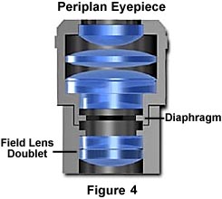
More advanced eyepiece designs resulted in the Periplan eyepiece that is illustrated in Figure 4 above. This eyepiece contains seven lens elements that are cemented into a single doublet, a single triplet, and two individual lenses. Design improvements in periplan eyepieces lead to better correction for residual lateral chromatic aberration, increased flatness of field, and a general overall better performance when used with higher power objectives.
Modern microscopes feature vastly improved plan-corrected objectives in which the primary image has much less curvature of field than older objectives. In addition, most microscopes now feature much wider body tubes that have greatly increased the size of intermediate images. To address these new features, manufacturers now produce wide-eyefield eyepieces (illustrated in Figure 1) that increase the viewable area of the specimen by as much as 40 percent. Because the strategies of eyepiece-objective correction techniques vary from manufacturer to manufacturer, it is very important (as stated above) to use only eyepieces recommended by a specific manufacturer for use with their objectives.
Our recommendation is to carefully choose the objective first, then purchase an eyepiece that is designed to work in conjunction with the objective. When choosing eyepieces, it is relatively easy to differentiate between simple and more highly compensated eyepieces. Simple eyepieces such as the Ramsden and Huygenian (and their more highly corrected counterparts) will appear to have a blue ring around the edge of the eyepiece diaphragm when viewed through the microscope or held up to a light source. In contrast, more highly corrected compensating eyepieces with have a yellow-red-orange ring around the diaphragm under the same circumstances.
Properties of Commercial Eyepieces
|
||||||||||||||||||||||||||||||||||||||||||||||||||
Table 1
The properties of several common commercially available eyepieces (manufactured by Olympus America, Inc.) are listed according to type in Table 1. The three major types of eyepieces listed in Table 1 are Finder, Wide Field, and Super Widefield. The terminology used by various manufacturers can be very confusing and careful attention should be paid to their sales brochures and microscope manuals to ensure that the correct eyepieces are being used with a specific objective. In Table 1, the abbreviations that designate wide field and super widefield eyepieces are coupled to their correction for high eye point, and are WH and SWH, respectively. The magnifications are either 10x or 15x and the Field Numbers (discussed below) range from 14 to 26.5, depending upon the application. The diopter adjustment is approximately the same for all eyepieces and many also contain either a photomask or micrometer reticle.
Light rays emanating from the eyepiece intersect at the exit pupil or eye point, often referred to as the Ramsden disc, where the pupil of the microscopists eye should be placed in order for her to see the entire field of view (usually 8-10 mm from the eye lens). By increasing the magnification of the eyepiece, the eye point is drawn closer to the upper surface of the eye lens, making it much more difficult for the microscopist to use, especially if they are wearing eyeglasses. To compensate for this, specially designed high eye point eyepieces have been manufactured that feature eye point distances approaching 20-25 mm above the surface of the eye lens. These improved eyepieces have larger diameter eye lenses that contain more optical elements and usually feature improved flatness of field. Such eyepieces are often designated with the inscription "H" somewhere on the eyepiece housing, either alone or in combination with other abbreviations, as discussed above. We should mention that high eye point eyepieces are especially useful for microscopists who wear eyeglasses to correct for near or far sightedness, but they do not correct for several other visual defects, such as astigmatism. Today, high eye point eyepieces are very popular, even with people who do not wear eyeglasses, because the large eye clearance reduces fatigue and makes viewing images through the microscope much more pleasurable.
At one time, eyepieces were available in a wide spectrum of magnifications ranging from 6.3x to 25x and sometimes even higher for special applications. These eyepieces are very useful for observation and photomicrography with low-power objectives. Unfortunately, with higher power objectives, the problem of empty magnification becomes important when using very high magnification eyepieces and these should be avoided. Today most manufacturers restrict their eyepiece offerings to those in the 10x to 20x range. The diameter of the viewfield in an eyepiece is expressed as a "field-of-view number" or field number (FN), as discussed above. Information about the field number of an eyepiece can yield the real diameter of the object viewfield using the formula:
where FN is the field number in millimeters, M(O) is the objective magnification, and M(T) is the tube lens magnification factor (if any). Applying this formula to the Super Widefield eyepiece listed in Table 1, we arrive at the following for a 40x objective with a tube lens magnification of 1.25: FN = 26.5 / M(O) = 40 x M(T) = 1.25 = a viewfield diameter of 0.53 mm. Table 2 lists the viewfield sizes over the common range of objectives that would occur using this eyepiece.
Viewfield Diameters
(SWF 10x Eyepiece)
|
||||||||||||||||||||||||||||
Table 2
Care should be taken in choosing eyepiece/objective combinations to ensure the optimal magnification of specimen detail without adding unnecessary artifacts. For instance, to achieve a magnification of 250x, the microscopist could choose a 25x eyepiece coupled to a 10x objective. An alternative choice for the same magnification would be a 10x eyepiece with a 25x objective. Because the 25x objective has a higher numerical aperture (approximately 0.65) than does the 10x objective (approximately 0.25), and considering that numerical aperture values define an objective's resolution, it is clear that the latter choice would be the best. If photomicrographs of the same viewfield were made with each objective/eyepiece combination described above, it would be obvious that the 10x eyepiece/25x objective duo would produce photomicrographs that excelled in specimen detail and clarity when compared to the alternative combination.
The "range of useful magnification" for an objective/eyepiece combination is defined by the numerical aperture of the system. There is a minimum magnification necessary for the detail present in an image to be resolved, and this value is usually rather arbitrarily set as 500 times the numerical aperture (500 x NA). At the other end of the spectrum, the maximum useful magnification of an image is usually set at 1000 times the numerical aperture (1000 x NA). Magnifications higher than this value will yield no further useful information or finer resolution of image detail, and will usually lead to image degradation. Exceeding the limit of useful magnification causes the image to suffer from the phenomenon of "empty magnification", where increasing magnification through the eyepiece or intermediate tube lens only causes the image to become more magnified with no corresponding increase in detail resolution. Table 3 lists the common objective/eyepiece combinations that lie in the range of useful magnification.
Range of Useful Magnification
(500-1000 x NA of Objective)
|
||||||||||||||||||||||||||||||||||||||||||||||||||||||||
Table 3
Eyepieces can be adapted for measurement purposes by adding a small circular disk-shaped glass reticle (sometimes referred to as a graticule or reticule) at the plane of the field diaphragm of the eyepiece. Reticles usually have markings, such as a measuring rule or grid, etched onto the surface. Because the reticle lies in the same plane as the field diaphragm, it appears in sharp focus superimposed over the image of the specimen. Eyepieces using reticles must contain a focusing mechanism (usually a helical screw or slider) that allows the image of the reticle to be brought into focus. Several typical reticles are illustrated in Figure 5 below.
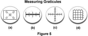
The reticle in Figure 5(a) is a common element of eyepieces intended to "frame" viewfields for photomicrography. The small rectangular element circumscribes the area that will be captured on film using 35 mm format. Other film formats (120 mm and 4 x 5 inch) are delineated by sets of "corners" within the larger 35mm rectangle. In the center of the reticle is a series of circles surrounded by four sets of parallel lines arranged in an "X" pattern. These lines are used to focus the reticle and image to be parfocal with the film plane in a camera back attached to the microscope. The reticle in Figure 5(b) is a linear micrometer that can be used to measure image distances, and the crossed micrometer in 5(c) is used with polarizing microscopes to locate the alignment of samples with respect to the polarizer and analyzer. The grid illustrated in Figure 5(d) is used to partition a section of the viewfield for counting. There are many other variations of eyepiece reticles, and the reader should consult the many manufacturers of microscopes and optical accessories to determine the types and availability of these useful measuring devices.
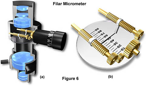
For highly accurate measurements a Filar Micrometer similar to the one illustrated in Figure 6 is used. This micrometer replaces the conventional eyepiece and contains several improvements over conventional reticles. In the filar micrometer, a reticle with a measuring scale (there are many variations in scale types) and a very fine wire is brought into focus with the specimen (Figure 6(b)). The wire is mounted so that it can be slowly moved across the viewfield by the calibrated thumbscrew located on the side of the micrometer (Figure 6(a)). One complete turn of the thumbscrew (divided into 100 equal divisions) equals the distance between two adjacent reticle marks. By slowly moving the wire from one position on the specimen image to another and taking note of the changes in thumb screw numbers, the microscopist has a much more accurate measurement of distance. Filar micrometers (and other simple reticles) must be calibrated with a stage micrometer for each objective with which it will be used.
Some eyepieces have a movable "pointer" located within the eyepiece and positioned so that it appears as a silhouette in the image plane. This pointer is useful when indicating certain features of a specimen, especially when a microscopist is teaching students about specific features. Most eyepiece pointers can be rotated in a 360 degree angle around the specimen and more advanced versions can translate across the viewfield.
Manufacturers often produce specialized eyepieces, often termed photo eyepieces, that are designed to be used with photomicrography. These eyepieces are usually negative (Huygenian type) and are not capable of being used visually. For this reason, they are typically called projection lenses. A typical projection lens is illustrated in Figure 7 below.
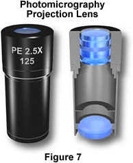
Projection lenses must be carefully corrected so that they will produce flat-field images, a definite "must" for accurate photomicrography. They are generally also color-corrected to ensure true reproduction of color in color photomicrography. Magnification factors in photomicrography projection lenses range from 1x to about 5x, and these can be interchanged to adjust the size of the final image in the photomicrograph.
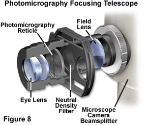
Camera systems have become an integral part of the microscope and most manufacturers provide photomicrographic attachment cameras as an optional accessory. These advanced camera systems often feature motorized black boxes that store and automatically step through film frame-by-frame as photomicrographs are taken. A common feature of these integral camera systems is a beamsplitter focusing telescopic eyepiece (see Figure 8) that allows the microscopist to view, focus, and frame samples for photomicrography. This telescope contains a photomicrography reticle, similar to the one illustrated in Figure 5(a) that is inscribed with a rectangular element that circumscribes the area captured with 35 mm film, and also corner brackets for larger format films. For convenience in scanning and photographing samples, the microscopist can adjust the telescopic eyepiece so that it is parfocal with the ocular eyepieces to make it easier to frame and take photomicrographs.
Contributing Authors
Mortimer Abramowitz - Olympus America, Inc., Two Corporate Center Drive., Melville, New York, 11747.
Michael W. Davidson - National High Magnetic Field Laboratory, 1800 East Paul Dirac Dr., The Florida State University, Tallahassee, Florida, 32310.
BACK TO ANATOMY OF THE MICROSCOPE