
Microscope Objectives
Nikon CFI60 200/60/25 Specification
The following material was supplied by the Nikon Instrument Group and has not been edited for the purposes of this tutorial. It is presented here only to inform our readers of the details of this new specification, and should not be taken as an endorsement by the authors.
Introduction - When typical microscopist speaks about Infinity Optics, they probably have this image of a dream optical system that can do anything. Some say performance increases when you use a microscope with an infinity optical system. So they conclude that if it's not an infinity optical system, it is not performing at a high level.
Are all manufacturers really trying hard to make this happen and to meet the expectations of users? Is it true that infinity optics significantly improve system flexibility, but is infinity optical performance always superior to finite optical systems?
Nikon CFI60 optical design team faced this proposition head on. They thoroughly studied the advantages and disadvantages of other manufacturers' systems, and found an optimum balance between optical performance and system flexibility. This document will help you understand why an infinity optical system, for biological applications, sets new performance standards incorporating a tube lens with a focal length of 200 millimeters, an objective with a parfocal distance of 60 millimeters, and an objective thread size of 25 millimeters.
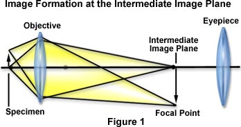
Why is the Focal Length of the Tube Lens 200 millimeters? - In a finite optical system, after light from an object passes through the objective, it is directed toward the primary image plane (often referred to as the intermediate image plane, located at the eyepiece focal point) and converges there as illustrated in Figure 1.
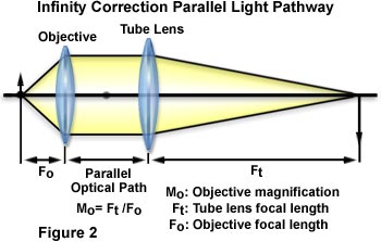
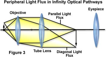
In an infinity optical system, however, light becomes a flux of parallel rays after passing through the objective and does not converge until after passing through the tube lens as shown in Figure 2. This does not mean that an infinite distance can be obtained after light passes the objective (up to the tube lens). After passing through the objective, light from an object on the optical axis moves parallel to this axis along the optical path. Light coming from the periphery of the object forms a flux of parallel rays and advances at a diagonal angle to the optical axis as diagrammed in Figure 3, presented below.
Because of this, there are instances where these rays of light can no longer be captured by the tube lens if the location of the tube lens is too far from the objective. This causes the image around the edges of the field of view to become dark or blurred, preventing the microscope from performing at its full potential. The term Infinity Optics simply means that light becomes a flux of parallel rays after passing through the objective, not that an infinite space is available inside the optical system.
If we are going to adopt infinity optics in order to further develop the microscope, we will need to increase the distance between the objective and tube lenses as well as increase the system flexibility. To lengthen this distance, we reduced the angle of the flux of parallel rays outside the optical axis. It is generally thought that a longer focal length for the tube lens will accomplish that, but this length has limitations.
The magnification (M(o)) of the objective in an infinity optics microscope is obtained using the formula:
where the tube lens focal length (F(t)) and objective focal length (F(o)) are described in Figure 2. If the focal length of the tube lens is lengthened, the distance to the image plane (at the eyepiece) will also increase with the longer focal length of the objective. Naturally, this makes the size of the microscope larger. With this in mind, the conclusion reached was that a focal length of 200 millimeters would be the most appropriate for the tube lens. The focal lengths adopted by other manufacturers are 160 millimeters and 180 millimeters.
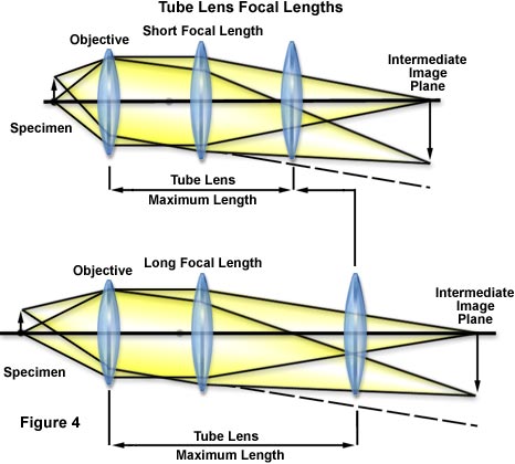
To obtain a same-size image from an object located far from the optical axis, the longer focal length of the tube lens produces a smaller angle of light against the optical axis. The light rays do not spread out so the distance between the tube lens and the objective can be increased greatly enhancing the potential for system flexibility as illustrated in Figure 4 below.
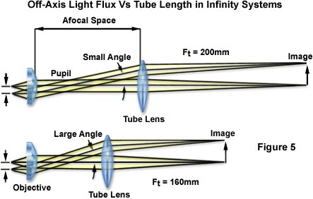
This design has certain optical advantages. As shown in Figure 5, when tube lenses of 160 millimeters and 200 millimeters focal lengths are compared, the 200 millimeters lens produces a flux of off-axis light rays with a smaller angle. In this context, light rays passing through the phase ring in a phase contrast attachment, the DIC prism in a Nomarski DIC attachment, or the dichroic mirror in an epi-fluorescence attachment, produce smaller shifts between light elements parallel to the optical axis and those diagonal to it, so that accessories work more efficiently. This is a big optical advantage, and also a primary factor contributing to an improved level of contrast in epi-fluorescence microscopy.
Why is the Parfocal Distance of the Objective 60 millimeters? - Once the tube lens focal length was set to 200 millimeters, the parfocal distance of the objective has to be increased from the standard 45 millimeters. As explained in the section on tube length, the focal length of the objective is also increased in order to preserve the same magnification, and since 45 millimeters does not provide optimum space in this design, a high-quality image cannot be obtained. In practice, the CF N Plan Apo 60x oil with a mechanical tube length of 160 millimeters, believed to be the ultimate in finite objectives, is crowded with lenses in a limited space of 45 millimeters. When this finite system is replaced with an infinite system and the objective is divided into an objective and a tube lens, the focal length of the tube lens becomes the equivalent of approximately 150 millimeters. On this basis, we can calculate the parfocal distance to provide an optical performance which surpasses that of the finite system as follows: The finite system objective parfocal distance is 45 millimeters; for a tube lens focal length of 150 millimeters, the infinite system objective parfocal distance is x; and the tube lens focal length is 200 millimeters. In solving this proportion, if 45 : 150 = x : 200, then x = 60 millimeters. Therefore, if the tube lens focal length is 200 millimeters, the optimum objective parfocal distance has to be 60 millimeters.
Using the calculations above the optimum parfocal distance for a tube length of 160 millimeters is 48 millimeters and for a tube length of 180 millimeters is 54 millimeters. For microscope manufacturers who set the objective parfocal distance in their infinity optics systems to 45 millimeters, then they are unable to exploit the full potential of their objectives.
Since the working distance (WD) also increases to match the longer objective focal length, manufacturers who use a parfocal distance of 45 millimeters are at a disadvantage in their inability to utilize the longer working distance achieved by Nikon. Using the Plan Apo 60x oil (N.A. 1.4) objective as a comparison, we see W.D.s by manufacturer to be at least 50 percent less than those of Nikon. This shows that there are differences in ability to accommodate various types of specimens as well as ease of operation.
Common Infinity Correction Tube Lengths
|
||||||||||||
Table 1
Low power lenses demand a specific size. If the magnification of the objective is 1x, the "M(o) = F(t)/F(o)" formula used in the tube length section shows that the focal length of the objective and that of the tube lens would have to be the same. In Nikon's case, in order to perfect a tube lens focal length of 200 millimeters, a parfocal distance of 45 millimeters would leave too little space in the design. By increasing this distance to 60 millimeters, a magnification of 1x is obtainable and thanks to this revolutionary change, an objective with a magnification as low as 0.5x has been achieved. The lowest magnification offered by other manufacturers is 1.5x and none of them has produced a 1x objective yet.
Why Use a 25 millimeters Objective Thread Size? - When the focal length of the tube lens is increased, the focal length of the objective must also increase. There is a limit to the objective pupil diameter (effective diameter remaining after the limits of the objective thread size), so a high numerical aperture (N.A.) cannot be obtained. Thus, the N.A. of low-power lenses is critically affected. At present, other manufacturers use a 20.32 millimeters thread size, but as mentioned above, Nikon uses 25 millimeters and is able to attain high numerical apertures. Originally, the brightness of photo lenses (F) was expressed with the formula:
where f is the lens focal length, and D is the effective diameter. Since the N.A. of a microscope corresponds to the F value of a photo lens, the brightness can be expressed with the formula:
The effective diameter needed to achieve a desired N.A. can thus be found using this formula. In other words, the size of the pupil on an objective (effective diameter on the exit side) is expressed as:
For example, to find the effective diameter of the CFI Plan Apo 4x (N.A. 0.2), objective with the highest (brightest) N.A.; given that the objective focal length is 50 millimeters, and where the focal length of the tube lens is 200 millimeters, the following calculation is made:
This shows that the conventional 20.32 thread size physically cannot be used. Pupil diameters required for designing 4x objectives with a numerical aperture of 0.2 based on 160 millimeters and 180 millimeters tube lengths are 16 millimeters and 18 millimeters respectively. This shows the kind of design problems faced by other manufacturers when using a conventional 20.32 millimeters thread size. The actual numerical apertures of the respective Plan Apo 4x objectives are 0.16. The N.A. for a Nikon objective in this class is 0.20, which is the highest in the industry.
As shown, to obtain a high numerical aperture, a low-magnification objective requires a large pupil diameter. The longer the focal length of the tube lens, the greater the necessity to enlarge the thread size on the objective. Nikon has solved this problem by choosing a 25 millimeters thread size for the CFI Infinity Optics system.
In Conclusion - We trust these explanations accompanied by specific examples have helped you to understand why a tube lens of focal length 200 millimeters is considered optimum for use in an infinity optical system and why higher optical specifications can be obtained with an objective parfocal distance of 60 millimeters and a thread size of 25 millimeters. Through JIS and other conventional standards have been followed for mechanical dimensions, the adoption of infinity optics itself has necessitated a sacrifice in compatibility with conventional systems.
Thus, rather than be bound by conventional dimensions, Nikon felt that its true task was to create products that users need for today's cutting edge microscopy techniques. Innovations in engineering, manufacturing, quality control, inspection, and production, have all contributed to the advent of Nikon's CFI60 series of optical systems.
Contributing Authors
Mortimer Abramowitz - Olympus America, Inc., Two Corporate Center Drive., Melville, New York, 11747.
Michael W. Davidson - National High Magnetic Field Laboratory, 1800 East Paul Dirac Dr., The Florida State University, Tallahassee, Florida, 32310.
BACK TO INFINITY OPTICAL SYSTEMS
BACK TO ANATOMY OF THE MICROSCOPE