
Image Brightness
Regardless of the imaging mode utilized in optical microscopy, image brightness is governed by the light-gathering power of the objective, which is a function of numerical aperture. Just as brightness of the microscope source illumination is determined by the square of the condenser working numerical aperture, brightness of the specimen image is proportional to the square of the objective numerical aperture.
Unlike the situation for the microscope illuminating system, however, objective magnification also plays an important role in determining image brightness. In fact, the image brightness is inversely proportional to the square of the lateral magnification:
where NA is the objective numerical aperture and M is the magnification. The ratio given in the equation above expresses the light-gathering power of the objective in transillumination (note: the case with epi-illumination is somewhat different, as discussed below). Examples of the light-gathering power of selected objectives having varying degrees of optical correction are listed in Table 1. In general, objectives with high numerical apertures are also better corrected for aberrations. Thus, for the same magnification, higher numerical aperture objectives collect more light, produce a brighter and better-corrected image (see Table 1), and the overall image is better resolved.
It is evident from examining the data in Table 1 that in cases where an objective is used for transillumination, image brightness decreases rapidly as the magnification increases in a series of objectives having identical correction. In contrast, utilization of a similar series of objectives for epi-illumination produces increasingly brighter images as the magnification increases through the lower ranges (10x through 40x), but tends to decrease at higher magnifications. Also apparent is a trend for objectives to produce much brighter images in epi-illumination (as opposed to transillumination) at the highest numerical aperture values.
The terms F(trans) and F(epi) that are utilized in Table 1 refer to the light-gathering power of an objective and were calculated according to the following equations:
F(trans) = 104 � NA2/M2
F(epi) = 104 � (NA2/M)2
In theory, the intensity of illumination depends on the square of the condenser numerical aperture and the square of the demagnification of the light source image (in effect, the field diaphragm image becomes brighter as it is made smaller, according to the square law). The result is that brightness of the specimen image is directly proportional to the square of the objective numerical aperture as it reaches the eyepiece (or camera system), and also inversely proportional to the objective magnification. Therefore, when examining specimens in transmitted light, changing the objective without altering the condenser affects image brightness in response to changes in numerical aperture and magnification.
Light-Gathering Power of Selected Objectives
|
|||||||||||||||||||||||||||||||||||||||||||||||||||||||||||||||||||||||||||||
Table 1
In the case of epi-illumination, the same considerations apply, except that the objective also acts as the condenser, and this must be taken into account when considering image brightness. As the objective magnification increases, the light source image is reduced (demagnified) by an equivalent amount, resulting in a brightness level that is less dependent on objective magnification and more dependent on numerical aperture (brightness is governed by the fourth power of numerical aperture in epi-illumination). In practice, the image brightness numbers vary (see Table 1) due to objective rear aperture size differences.
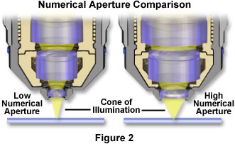
When the light level is limiting, the highest numerical aperture objective should be employed, yet the magnifications of the both the objective and eyepiece should be kept at the lowest level compatible with the desired resolution. In many cases, manufacturers are now providing oil immersion objectives with higher numerical apertures, and correspondingly higher image brightness values, than high-dry counterparts of similar magnification. For example, the 40x plan apochromatic immersion objective in Table 1 has twice the numerical aperture of the plan achromat 40x dry objective, and produces four times the image brightness in transmitted light. These objectives yield a 16-fold difference in image brightness under epi-fluorescence illumination, with the high numerical aperture oil immersion version producing the brightest images. Figure 2 presents a comparison of the relative differences in light cone sizes between low and high numerical aperture objectives. Note that the higher numerical aperture objective has a much larger light cone, larger internal lens elements, and is capable of gathering far more light from the specimen than the objective having a lower numerical aperture.
The amount of light transmitted through the optical components of the microscope, as a function of incident intensity, is especially critical in fluorescence microscopy. In situations where high-resolution fluorescence imaging requires high magnifications with a minimal loss of image brightness, the highest numerical aperture objectives having the greatest degree of light transmission should be employed. As discussed above, overall image brightness decreases rapidly as magnification increases, so the components of a fluorescence microscope should be carefully chosen to maximize the amount of light passing through the optical train.
| Interactive Tutorial |
|
||||||||||
|
|||||||||||
As discussed above, fluorescence microscopes that utilize epi-illumination are equipped with objectives that serve the dual purpose of both condenser and objective. Light passing through the excitation filter and reflected from the dichromatic mirror surface in the filter cube is first passed through the objective to form an inverted cone of illumination necessary to excite the specimen. Secondary fluorescence emitted by fluorophores attached to the specimen is then gathered by the same objective lens system and passed back through the dichromatic mirror and barrier filter before being projected into the eyepieces or the imaging system. A high numerical aperture objective acting as a condenser will increase the signal (light) intensity in a manner that is proportional to the square of the numerical aperture. Because the light gathering power of the objective is also proportional to the numerical aperture squared, image brightness will vary as the fourth power of the objective numerical aperture according to the equation:
Note that in fluorescence microscopy, brightness is also inversely proportional to the objective magnification squared. Thus, for objectives of identical magnification, image brightness of both the illumination field and the fluorescence image increases dramatically with objective numerical aperture, which is the primary reason manufacturers produce objectives designed with very high numerical apertures for fluorescence microscopy.
The eyepieces employed to observe the specimen further magnify the diffraction-limited image projected into the microscope intermediate image plane, and also serve to decrease the overall observed intensity of the specimen. In fact, image brightness is inversely proportional to the square of the eyepiece magnification, requiring the use of eyepieces having the lowest possible magnification necessary to conveniently observe specimen fluorescence. It is therefore possible to maximize image brightness in fluorescence microscopy by using the highest available numerical aperture objective coupled to the lowest power eyepieces (although 10x eyepieces are most commonly employed). These remarks apply primarily to large specimen areas that have an even degree of illumination. In the case of sharply focused point sources of light (for example, minute fluorescent spheres), the particle images should be diffraction-limited and have dimensions that are independent of magnification.
Increasing the Specimen Signal
In fluorescence microscopy, image brightness is determined by the intensity of illumination, the quantum yield of the fluorophore, and the light-gathering power of the microscope. The greater the intensity of illumination and the higher the quantum yield, the greater the fluorescent signal and the brighter the image becomes until all of the fluorophores are saturated. Likewise in polarized light, image brightness is governed by the illumination intensity and birefringence retardation of the specimen. At values up to a quarter-wavelength of retardation, larger retardations produce a greater birefringence, and thus a stronger signal.
In both of these cases, image brightness is controlled by the signal from the specimen, which is a product of the intensity of illumination and the change in light introduced by the specimen. In the case of luminescence, where the specimens themselves emit light, image brightness is clearly governed by the magnitude of light, or the signal, emitted by the specimen.
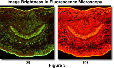
This concept is illustrated in Figures 3 and 4 for fluorescence and polarized light specimens, respectively. Presented in Figure 3 is a pair of digital images from an oleander leaf thin section taken under epi-illumination conditions on a stereomicroscope equipped with a fluorescence illuminator. When the thin section is excited with an Endow green fluorescence protein (GFP) filter set having a bandpass range between 450 and 490 nanometers, the specimen exhibits a weak green autofluorescence (Figure 3(a)) that is highly visible in some portions of the specimen, but very weak in others. In contrast, excitation of the specimen with a longer wavelength bandpass filter set (530-560 nanometers; Figure 3(b)) produces a bright red autofluorescence with a much stronger signal throughout the thin section.
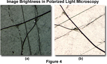
A similar situation is observed with polarized light microscopy of mineral thin sections, as illustrated in Figure 4. The specimen is a polished 30-micron section of anorthosite, an igneous rock composed almost entirely of feldspar. When the highly oriented birefringent thin section is positioned with the optical axes perpendicular to the polarizer, light (the signal) passing through the analyzer is minimized (Figure 4(a)). However, when the optical axes are oriented in a 45-degree angle with respect to the analyzer and polarizer (Figure 4(b)), the maximum amount of light is received by the eyepieces or image sensor.
In other modes of microscopy, such as phase contrast, differential interference contrast (DIC), darkfield, Hoffman modulation contrast, etc., the intensity of illumination and image contrast can be varied independently. Nevertheless, the signal from the image, namely, the increment of image brightness per unit of variation in an optical parameter (for instance, a difference in path length), would still be determined by the product of the illumination intensity and the contrast produced per unit variation in the optical parameter. To detect small variations in any optical parameter, the microscopist should maximize the signal arising from variations in that particular parameter.
Light Transmission Through the Microscope
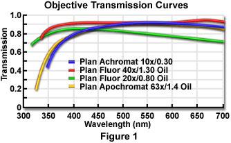
For a given condenser and objective numerical aperture, magnification, and illuminator brightness, image brightness produced by the microscope can still vary depending on the light transmission through the optical components. Light transmission depends on several factors, including absorption by lens elements and cements, reflection losses at the optical interfaces, and transmittances of the lamp jacket, diffusing screen, filters, polarizers, and other auxiliary optical components. Typical transmission curves for a selected set of high numerical aperture objectives are illustrated in Figure 1. These values are more or less representative of any class of objectives from a particular manufacturer, but even among the specific types for which these curves were measured, the exact transmission values can vary somewhat depending on, for example, the antireflection coating and the batch of glass used in individual lenses.
The transmittance (intensity transmitted as a percentage of incident intensity) of some optical components can be wavelength-dependent even within the visible range, as shown in Figure 1. Also, at wavelengths outside the visible range, the transmittances of lenses, prisms, slides, and the mounting medium for the specimen can drop appreciably. This fact is exemplified by the 20x plan fluor objective transmission curve illustrated in Figure 1, which shows a steady decrease in transmittance as the wavelength is increased between 400 and 700 nanometers. Other objectives in the series do not exhibit such a marked degree of wavelength dependence.
More than 200 optical glass formulations have now been developed and are available to the optical designer for incorporation into microscope lenses, mirrors, filters, and beamsplitters. The properties of these glasses, such as refractive index, dispersion, transmission, contaminants, potential for autofluorescence, chemical and thermal resistance, and overall homogeneity are usually carefully selected to ensure maximum optical performance. However, these factors often compromise other requirements, such as high transmission in the near ultraviolet range or high extinction factors in polarizing microscopy. Some new materials, such as fluorocrown glass, approach the properties of natural fluorite while avoiding most of its drawbacks, such as the presence of organic contaminants and a crystalline microstructure, which can seriously degrade performance in fluorescence and polarizing microscopy. Fully apochromatic correction, however, still requires both natural fluorite and glasses that have reduced transmission in the near ultraviolet range. An ideal compromise is often the semi-apochromat or fluorite objective, which is a true multi-purpose objective, combining excellent correction with good contrast, high numerical aperture values, and a high spectra throughput.
Even though optical cement thicknesses average only about 10 microns or less, the cements placed between doublet or multiple lens elements can have spectral absorption properties that may render an objective unsuitable for specific applications. In most cases, the chemical and optical properties of optical glasses, and some optical cements, are usually proprietary.
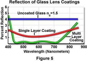
All surfaces at glass-air interfaces reflect some light and result in loss of transmission, even when there is no absorption of light and the beam is incident normal to the interface. As the angle of incidence increases, the reflection and transmission losses increase in a manner that is dependent upon the orientation of light wave vibration directions (perpendicular or parallel to the plane of incidence). Each uncoated air-glass interface can reflect between four and five percent of a light beam incident perpendicular to the surface (see Figure 5). The transmittance per passage through an untreated interface would thus be 95 to 96 percent at normal incidence. By applying an antireflection coating (usually a quarter-wave thick interference film with an appropriate refractive index), light reflection at the glass surfaces can be reduced to one percent or less for a moderate range of wavelengths and incidence angles, as illustrated in Figure 5 for a wavelength range between 400 and 850 nanometers.
Multilayer antireflection coatings have been developed, which can reduce the reflection at an air-glass interface to values as low as 0.1 percent over an even wider range of wavelengths. A majority of the commonly utilized multilayer interference coatings have a slightly greenish tint, as opposed to the purplish tint of single-layer coatings, making them easier to identify. Some antireflection coatings, especially multilayer ones, behave anisotropically for non-normal incident waves and can drastically lower the extinction factor in polarization-dependent optical systems.
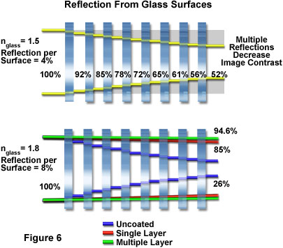
As objective sophistication increases, more lens elements are required, and this accentuates the need to eliminate internal reflections to produce higher transmission, better contrast, and less flare. These properties are particularly important for incident or reflected light applications. Single layer antireflection coatings dating back to the 1940s have since been refined and supplemented by multilayer coatings, increasing the transmission in the visible spectral range through an air-glass interface from around 96 percent (not coated) to almost 99.9 percent (utilizing multilayer coatings, as described above and illustrated in Figures 4 and 5). Figure 6 illustrates the effects of multiple reflections on glass surfaces having refractive indices of 1.5 and 1.8 (upper and lower drawings, respectively). At the lower refractive index (1.5), the eight elements with their 16 surfaces, each reflecting approximately four percent of the incident light, results in a throughput of only 52 percent. In contrast, the higher refractive index glass elements (1.8), the 16 uncoated surfaces will pass only 26 percent of the incident light. The single layer antireflection coating increases transmission to 85 percent, while the multilayer coating increases this value to about 94.6 percent. This increase in throughput and corresponding reduction in internal scatter and noise substantially enhances the contrast of an image because it makes bright features brighter and dark features darker.
Coating materials are either magnesium fluoride or a multitude of proprietary materials, all of which have their own optical properties potentially affecting the transmission of the optical system in given spectral regions. In general, the interference characteristics of antireflection coatings are spectrally limited, and constructive interference for high transmission in the visible range means destructive interference in harmonically-related frequencies outside the transmission band.
A majority of modern high numerical aperture objectives having a high degree of correction for optical aberration contain up to 15 individual lens elements and as many as 10-12 air-glass interfaces. If the lenses were uncoated, reflection losses of axial rays alone would drop the transmittance of these objectives to about 50 percent. With all the surfaces coated using single or multilayer interference films, the transmittance can be improved to about 86 to 90 percent.
In addition to those lens elements found in objectives, there may exist between two and four dozen glass-air interfaces in the optical train of modern microscopes:
Lamphouse and Collector - 4-6 individual lens elements
Internal Optical Train - 2-8 mirrors, prisms, and relay lenses
Filters - 2-8 units in transmission or epi-fluorescence
Beamsplitters - 1-4 units in observation tubes and camera systems
Condensers - 4-8 lenses, depending on optical correction
Specimen - 0-4 including the slide and coverslip
Eyepieces - 4-6 depending on optical correction and design
Camera System - 2-6 lenses, mirrors, and filter elements
In extreme cases, there can be as many as five dozen optical interfaces when the objective is included. Less than 9 percent of the axial rays would be transmitted through a microscope with 60 uncoated interfaces, and a little over 50 percent with all the surfaces coated.
High quality lens coatings are essential not only for improving the transmission of light through the microscope, but also for decreasing the flare due to multiple reflections at the glass surfaces. However, even the best coatings will not work beyond a certain wavelength range. For some wavelengths, the coating can even increase the reflectance (a half-wave interference film is a perfect reflector). This is an important point to keep in mind for digital imaging with CCD cameras, photodiodes, photomultipliers, or video sensors, where the sensitivity of the photodetector can peak at wavelengths quite far from that of the human eye.
In addition to reflection losses at the optical interfaces, blockage of light transmission through the lamp jacket may reduce image brightness. As the lamp ages, the glass or quartz jacket may craze or darken as it devitrifies or becomes coated or permeated by atomized metal evaporating from the filament or electrodes. It is worth noting that the transmittance of the lamp jacket may drop sooner in the ultraviolet than the visible regions. In this case the visible brightness, or luminance measured with a photometer, may be a poor indicator of the ultraviolet output of mercury or xenon arc lamps.
A ground-glass diffusing screen transmits only 10 to 15 percent of the light traveling within three percent of its normal. Even less light is transmitted at oblique incident angles. Thus, ground-glass diffusers should be avoided whenever the level of illumination must be maximized.
Filters and dichromatic mirrors have transmissions that fall as the passband is narrowed. Many interference filters transmit only 15 to 30 percent of the incident energy at the wavelength for peak transmission. However, some selected multilayer interference filters with half-transmission bandwidths as narrow as 50 angstroms can provide peak transmittance of 75 percent or greater.
The polarizing filters used in polarizing and differential interference contrast (DIC) optics can also substantially reduce transmission of light through the microscope. Even when the polarizer and analyzer axes are set to a parallel position at peak transmission, the transmittance of a polarizing filter set, each with a natural light transmittance of 20 percent, is only about 8 percent. In contrast, high-quality calcite prisms with antireflection-coated cover plates can transmit the theoretical maximum of about 50 percent of the incident unpolarized light per pair.
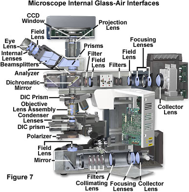
Presented in Figure 7 is an illustration of the internal lens elements in a modern optical microscope configured for both transmitted and reflected light illumination and observation. Note the extensive number of glass-air interfaces present in the microscope base between the lamp and the field lens and a similar number in the vertical illuminator. There is also a large number of interfaces in the windows, prisms, and lenses of the observation tubes and eyepieces, as well as the nosepiece and condenser assemblies.
As discussed above, a variety of factors can limit light transmission through the many optical components of a modern microscope. Where one is striving for the highest resolution, especially in contrast enhancing modes where the image is inherently dim, all of the factors previously listed should be examined carefully. It should be reiterated that transmittance through the entire microscope is determined by the product of the transmittances of all the optical components.
Brightness of Illumination
In a microscope equipped with a well-corrected illuminator (including the collector lens system) and condenser lenses, the degree of illumination (illuminance) of the field under conditions of K�hler illumination is governed by a number of factors including the intrinsic brightness (mean luminous density) of the light source and the focal length of the collector lens for the light source. In addition, the numerical aperture of the condenser lens system, the setting of the condenser aperture iris diaphragm opening size, and the overall transmittance of the illumination system help control the degree of illumination.
Under K�hler illumination, light emanating from each point on the source uniformly illuminates the microscope field diaphragm to produce a bright and evenly distributed field of illumination (depending upon the nature of the light source). Therefore, the size of the opening in the field diaphragm affects only the diameter of the illuminated field and not its brightness.
Luminous Density of Selected Light Sources
|
|||||||||||||||||||||||||||
Table 2
Provided the focal length of the collecting lens is not too short to project an image of the source that covers the entire opening of the condenser iris diaphragm, the collecting power, or f value (diameter/focal length) of the lens does not affect the illuminance of the field. The mean luminous density of the light source and the square of the condenser numerical aperture determine the illuminance of the field, provided the condenser iris opening is filled with the image of the light source. The collecting power of the collecting lens and the size of the light source affect the field illuminance only if the image of the source does not cover the entire condenser aperture.
In summary, the mean luminous density (the light output per unit area of the source) determines image brightness, not the total light output, the luminous flux, or the area of the light source. The luminous flux from the source is the product of the luminous density and the area of the source, with the latter playing only a secondary role in determining the mean luminous density. Because the luminous density of the source limits the field illuminance, the luminance of the image can never exceed the luminous density of the source. In other words, the field can never be brighter than the source, no matter what clever arrangements and combinations of mirrors, prisms, lenses, or other components are employed in the optical train. Table 2 lists several illumination sources having relatively high luminous density that are useful in optical microscopy, and includes specifications such as luminous flux, arc size, and mean luminous density.
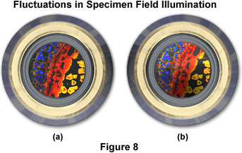
It should be noted that many concentrated arc lamps (mercury and xenon) provide a very high degree of luminous density, and have a highly non-uniform degree of light distribution over the arc. Commonly, the arc is brightest in a minute spot adjacent to one of the electrodes, even within arcs whose overall dimensions are small (as low as 0.3 x 0.3 millimeters). When the image of such an arc is projected into the condenser aperture, there is no longer an even distribution of illumination intensity. Thus, the diffraction pattern produced by each point in the specimen departs from the ideal Airy disk. Nevertheless, these arc lamps are essential for certain applications in microscopy (primarily fluorescence) because of the high mean luminous density. A remedy for this situation is to employ a single optical fiber (not a fiber bundle) light scrambler that can be added to the microscope without appreciable loss of mean illuminance. Figure 8 illustrates a fluorescence image at the objective rear focal plane in a situation where field illumination is not uniform due to uneven distribution of illumination intensity. In Figure 8(a) the specimen image is evenly illuminated and will project an acceptable image onto the sensor. Conversely, in Figure 8(b), the specimen is not properly illuminated across the viewfield and will result in an image that has a significant degree of fluctuation in intensity.
The microscope substage condenser is a critical element in determining the quality and degree of illumination provided to the specimen. Some microscope condensers can be employed with and without an immersion medium between the condenser top lens and the objective front lens. More often, higher-quality condensers are designed to be used with a particular immersion medium, having a specific refractive index and dispersion. The medium, which can be oil, glycerol, water, or air, fills the space between the condenser top lens element and the lower surface of the specimen slide.
A majority of darkfield, and some phase contrast, differential interference contrast (DIC), and polarized light optics require the condenser to be immersed in order to achieve a high condenser numerical aperture. The condensers are designed for optimum performance and minimum aberration when the correct immersion medium having a defined refractive index and dispersion is utilized. Immersion dispenses with the loss of light past the critical angle, eliminates additional refraction, minimizes reflection losses of light, and reduces the number of optical interfaces that can scatter or reflect light at high angles of incidence. Such scattering and reflection become a source of flare, and also alter the state of polarized light, thus reducing the extinction in high numerical aperture polarization optical systems. In summary, immersion of the condenser affects the field illuminance as well as the quality of the image. To achieve maximum performance, condensers designed to be immersed should be immersed with the correct medium.
Although the illuminance of the field rises with the square of the condenser numerical aperture, opening the condenser iris diaphragm too far beyond the matching objective numerical aperture produces flare. Furthermore, the portion of the illumination that misses the objective aperture produces a darkfield image superimposed on the brightfield image, thereby reducing image contrast.
Conclusions
The area exposed on a video sensor or photographic film plane in the optical microscope is proportional to the square of the magnification, as discussed above. Image brightness therefore decreases with the square of the magnification. In general, microscopes are utilized to expose the fine details in a specimen, but at the same time, the microscope is a potent light-gathering instrument. Just as a telescope or binocular improves our vision at night, the light-gathering power of the microscope can be effectively employed to capture the image of faintly illuminated objects.
Depending upon the features of the specimen that must be visualized, the image may become more meaningful if more light is collected rather than raising the magnification. For a number of luminescent and fluorescent specimens, the light level may be so low that a highly magnified image becomes invisible or undetectable, and hence totally meaningless. In such cases, the image can be made more intelligible by collecting more light by either integrating the light over time (if the specimen is static), or by reducing the magnification of the image.
For extremely low-light-level situations, one can maximize image brightness by using the highest numerical aperture objective available at the lowest overall magnification. In some cases it is even beneficial to use the ocular to reduce, rather than increase, the magnification of the intermediate image.
In an effort to match the sensor resolution to the resolving power of the objective, there is a general tendency to boost the magnification of the image projected onto the CCD sensor or video pickup device. Because image brightness drops by the square of the magnification and the sensor can only function within a restricted range of intensities, increasing the magnification can result in the brightness level dropping below the sensitivity of the sensor. If the specimen is stationary or changes very slowly, the signal-to-noise ratio can be dramatically improved by integrating the image over several frame times, either by summing or averaging the signal, or better yet, by integrating photoelectrons in the sensor itself. In this case, temporal resolution is sacrificed to improve spatial information. Regardless, there is often a tug-of-war, and compromise, between attempts to increase resolution and attempts to reduce the noise level, which rises dramatically as the image grows dimmer. When brightness from the image is limited, the microscopist must carefully fine-tune the instrument magnification to strike the best balance.
Contributing Authors
Kenneth R. Spring - Scientific Consultant, Lusby, Maryland, 20657.
H. Ernst Keller - Carl Zeiss Inc., One Zeiss Dr., Thornwood, NY, 10594.
Michael W. Davidson - National High Magnetic Field Laboratory, 1800 East Paul Dirac Dr., The Florida State University, Tallahassee, Florida, 32310.
BACK TO ANATOMY OF THE MICROSCOPE