INTRODUCTION TO PHOTOMICROGRAPHY
![]()
Michael W. Davidson
Institute of Molecular Biophysics
and Center for Materials Research and Technology
The Florida State University,
Tallahassee, Florida 32306
Telephone: 850-644-6114 / Telefax: 850-644-8281
Recent developments in the materials sciences have led to an enhanced interest in this rapidly growing field. In this respect, the discovery of high-temperature superconducting ceramics coupled to an almost explosive progress in semiconductor and integrated circuit technology has shifted an enormous amount of attention to these disciplines. Visible light microscopy is an invaluable tool for the investigation of samples in the materials sciences and engineering. An introduction to photomicrography at the high school level could provide interested students with a useful preview to research techniques in these areas.
INTRODUCTION
The biological and medical sciences have, for many years, relied heavily on microscopy to solve problems relating to the gross morphological features of specimens as well as a quantitative tool for recording specific optical features and data. In this respect, the transmitted light microscope has proven useful in countless investigations into the mysteries of life.
More recently, microscopy has been employed in the physical and materials sciences as well as the semiconductor industry to examine various aspects of new materials as, for example, birefringent liquid crystalline systems [1], high temperature superconductor thin-films [2], and integrated circuit surfaces [3,4]. The nature of these materials requires, in some instances, examination by reflected (episcopic) illumination that departs from the classical transmitted (diascopic) illumination techniques that have been so well developed in the biological sciences.
Transmitted light microscopy is a mature discipline in which a wide spectrum of illumination techniques are available for contrast enhancement. For instance, living cells in tissue culture can be observed directly at amazingly high resolution using phase and differential interference contrast techniques. At high magnification, cellular internal features are clearly resolvable using these methods.
In contrast, reflected light microscopy is just emerging as an important tool for investigating surface features in the materials sciences. A significant boost to reflected light microscopy has come from the semiconductor industry which relies heavily on this technique to capture microscopic details on integrated circuit wafers during the manufacturing process. The need for contrast enhancement methods in reflected light microscopy has led to the development of reflected light differential interference contrast objectives that rival, in quality, their counterparts on the transmitted light microscope.
Photomicrography has enjoyed a recent escalation in popularity due, in part, to the introduction of new transparency films with improved emulsions that respond correctly to the color spectrum generated by tungsten-halide light bulbs found in most microscopes. Improved glass alloys and optical coatings have enabled manufacturers to provide microscope objectives that will produce crisp images of better quality than has been previously possible. These developments coupled to the wide-spread availability of microprocessor-assisted internal microscope exposure monitors have collectively been directly responsible for the increased activity in the field of visible light photomicrography.
Computer-assisted image analysis and confocal microscopy [5,6] are surfacing as important techniques, however their high cost will prohibit their entry into the high school arena in the foreseeable future. Therefore, this discussion will be limited to various aspects of photography using both transmitted and reflected light microscopy.
MICROSCOPE CONFIGURATION
The majority of microscopes found in public schools are of the transmitted light variety commonly used in biological laboratories. At relatively low cost, these microscopes can be converted for use in the materials and geological sciences as well.
Most microscope light sources emit visible light that vibrates as a wave in all directions perpendicular to the optical axis of the microscope. When used in this fashion, the microscope is said to be operating in the brightfield mode. Placing a polarizing element into the light path restricts the passage of light, much as an optical slit, to those waves that propagate in the vector plane of the polarizing element. This action reduces the amount of transmitted light to approximately 30% of the emitted value.
A common microscopy technique involves the use of crossed polarizers where two individual polarizing elements are inserted into the light path with their vector propagation planes crossed at a 90 angle with respect to each other. When a sample is placed in the light path between the crossed polarizers, the only light emitted will be that which is refracted by the sample until it can pass unimpeded through the second polarizer. In classical nomenclature the first polarizer has been termed the polarizer while the second polarizer is termed the analyzer.
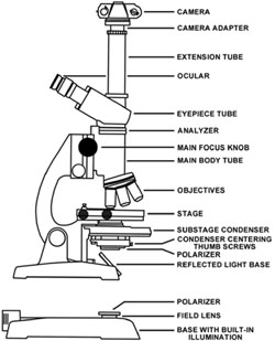
Any brightfield microscope can easily be converted for use with polarizing elements. Two polarizers will be needed to convert the microscope for use with polarized light. The polarizer responsible for polarizing the light emitted from the microscope light source is placed either directly on the field lens or can be taped (with masking tape) to the substage condenser (refer to Figure 1 for a detailed microscope description). On microscopes with an internally directed lamp, it is sufficient to place a polarizer onto the field lens as is illustrated in Figure 1. This polarizer should be large enough to cover the lens completely.
|
Schematic illustration of a transmitted light microscope. |
Low cost polarizers designed for camera lenses are sufficient for this purpose. But, if an external light source is reflected into the substage condenser through a mirror (Figure 1), it becomes necessary to tape a polarizer onto the bottom of the condenser. Many science supply houses and distributors offer an excellent selection of polarizing materials at somewhat low cost. When purchasing polarizing elements, remember to select materials that are as close to a neutral grey as possible. Avoid materials that are amber or green in color. These off color materials will cause color shifts that must be corrected for in color photomicrography.
The second polarizer (which is termed the analyzer, as described above) is inserted inside the body of the microscope between the main body tube and the eyepiece tube. There is usually a lens mount covering the top main body tube and the analyzer can be taped or simply rested directly on this mount. Because of the restricted space within the main body tube, the analyzer is limited in physical size to 1-3 cm in diameter. An analyzer of this size can be obtained by cutting a small section from a sheet of polarizing material or by purchasing a small polarizer from a dealer.
The analyzer and upper main body lens should be thoroughly cleaned to eliminate dust and fingerprints before reassembly of the microscope. After both polarizers are in place, activate the microscope light source, place a specimen on the stage, and view directly into the oculars (eyepieces). Next, bring the image into focus and rotate the polarizer on the microscope base until the viewfield becomes very dark (maximum extinction). At this point, the polarization direction is perpendicular between the polarizer and analyzer and you then have crossed polarizers as described above. Some microscope manufacturers offer a low budget polarization kit ($150.00 to $300.00) that is easily user installed. It is advisable to contact your microscope's distributor or manufacturer concerning the availability of these items if your budget is healthy.
Among the useful methods of enhancing sample contrast are the interference methods in which contrast augmentation is similar to that observed in phase contrast microscopy with the elimination of edge "halo" effects. Differential interference contrast microscopy requires expensive objectives equipped with a special set of prisms termed Wollaston prisms that are optically matched to each objective [7]. A relatively low-cost substitute for the interference contrast effect generated by the Wollaston prisms involves adapting a polarized light microscope with Savart plates serving in place of the polarizers. Savart plates are flat plates of a suitable quartz crystal cut and polished to produce the necessary divided interference beams of light in order to generate the three-dimensional effect of interference contrast. Savart plates are commonly available from optical supply houses.
The renovations described above apply only to transmitted light microscopy where polarized visible light passes directly through the sample. In reflected light microscopy, the light beam is reflected from the surface of the sample directly into the microscope objective. It is not a straightforward process to convert a biological transmitted light microscope for use with either polarized or interference contrast reflected illumination methods. To avoid investing in expensive reflected light attachments, oblique illumination from an external light source can be substituted to produce the reflected light effect.
A high-intensity light source such as a fiber optics lamp (available for under $200.00) provides an excellent substitute. To achieve a semi-polarized light effect, the analyzer can be left in place and polarizers attached (by tape) to the external light source. Before final attachment, the polarizers should be rotated as described above to produce maximum extinction. Unpolarized room light, that will unavoidably be reflected into the objective, will slightly diminish the total amount of light extinction. This method of microscopy is particular well suited for examination of integrated circuits and other specimens that possess intricate surface detail.
Common biological stereo-binocular (dissecting) microscopes are also useful for reflected light examination of materials science samples. These microscopes are particular useful for photomicrography of the larger integrated circuits such as microprocessors. To adapt a stereo microscope for polarized light, tape a large polarizer (such as a model designed to mount onto a (camera lens) onto the lower portion of the main body tube. Insure that the polarizer completely covers the lens mounted in this lower portion of the tube. Next, adapt a polarizer to the external light source. If fiber optics illumination device is used, simply tape the polarizer over the end of the fiber outlet tube.
Fiber optics sources can be obtained that have a beamsplitter to divide the output light into two tubes. These sources are ideal for illumination of samples with reflected light because a sample can be illuminated from several directions to eliminate a shadow effect. In this case, be sure to cover both fiber outlet tubes with a polarizer. Place a mirror on the stage to reflect light directly into the objective and rotate the polarizers on the fiber outlet tubes until maximum extinction is reached. It is usually easier to block the light from one tube and adjust the other for maximum extinction, repeating the process again for the blocked tube.
Attaching a camera to the microscope is the last step. Microscope viewing heads come in three varieties: monocular (one eyepiece), binocular (two eyepieces), and trinocular (two eyepieces and a photography tube). A camera can be adapted to each of these viewing heads. Commercially available aftermarket camera adapters usually are attached to one of the viewing tubes with a thumbscrew and adjusted to be parfocal with the eyepieces by sliding the adapter up or down on the viewing tube. A simple camera back will be sufficient for photomicrography because the camera is required only to store, expose, and advance the film. The microscope itself acts as a camera lens. After a camera back has been adapted to a microscope, one should not rely on exposure values computed by in camera exposure monitors. It is best to bracket exposures to get a handle on exposure times as is discussed in the section on photomicrography. For optimal photomicrography, it is very important to insure that your microscope is aligned to produce an even illumination across the viewfield. Information on microscope alignment is available in owners manuals or in textbooks dealing with microscopy and photomicrography [8].
PREPARATION OF SAMPLES FOR PHOTOMICROGRAPHY
The laboratory chemicals found in high school chemistry stockrooms provide an excellent source for samples. Most crystals are anisotropic and birefringent which means that they will refract plane-polarized light emitted from the polarizer and will "bend" it until it is visible through the analyzer under cross-polarized illumination.
To prepare crystals for examination in the microscope, deposit a few milligrams of the appropriate chemical on a glass microscope slide and carefully place a coverslip over the powder. Next, heat the bottom side of the microscope slide carefully with a bunsen burner or hot plate until the powder has completely melted. Some chemicals decompose upon heating and will provide poor subjects for microscope examination. Salts are notorious as bad candidates for the melt-recrystallization process. The melting point of most salts is usually very high and any organic portion of the molecule undergoes degradation before melting. When melted, the molten chemical will flow underneath the coverslip and fill the entire volume between the coverslip and microscope slide. Either allow the slide to cool slowly before examination or place the melted chemical sandwich onto the microscope stage and examine the crystallization process occurring [9].
Certain chemicals recrystallize very rapidly (within a few minutes) while others may recrystallize slowly over a period of days, weeks, or even months. Urea, sulfur, and benzoic acid are excellent examples of common laboratory chemicals that will recrystallize rapidly enough to be examined directly after melting. Some chemicals form more interesting crystals when cooled slowly over a period of hours or days. This can be accomplished by placing the microscope slide with it's melted chemical sandwich on a hot plate at 50-70 ºC and reduce the temperature by 5-10 ºC/hr over a period of several hours. By comparing the slowly recrystallized sample to one that was rapidly recrystallized, any differences in recrystallization can be noted. The instructor and students should experiment with available chemicals to identify those that are optimal for microscopic analysis.
|
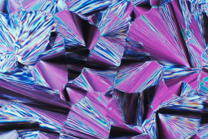
Transmitted polarized light micrograph of a high density liquid crystalline DNA phase. |
Another very effective method of preparing crystals is to dissolve the chemical in a suitable solvent such as water, ethanol, acetone, or mineral spirits. A drop of the solution is then sandwiched between the microscope slide and coverslip and the solvent allowed to evaporate resulting in formation of crystalline patterns. This method is especially useful for chemicals in the salt family that usually decompose upon heating leaving a tar-like mess. In some instances, increasing the time for solvent evaporation will result in a dramatic increase in crystallite size. The evaporation time can be controlled by partially sealing the coverslip with a bead of polymethylmethacrylate mounting medium leaving only a small edge of the coverslip exposed to the atmosphere. This will retard solvent evaporation to allow a slower recrystallization process to occur usually resulting in larger, more well-formed crystallites.
The colorful crystalline pattern illustrated in Figure 2 derives from a highly concentrated liquid crystalline DNA sample in which the aqueous solvent was allowed to evaporate slowly as described above. Under these circumstances a dilute solution of DNA will undergo a series of liquid crystalline phase transitions until a concentration is reached that is depicted in Figure 2. DNA exists in nature at very high concentrations, and it is possible that liquid crystalline DNA phases have an invaluable function in biological systems [10-13]. Many chemicals can display a wide spectrum of polymorphic crystalline patterns depending on whether they are melt-recrystallized or recrystallized by solution evaporation.
Samples for reflected light microscopy usually require very little preparation. Reflected light microscopy can be likened to topographical surface examination with a high-power magnifying glass, and almost anything can be examined in microscopic detail with this technique. For example, the fine details of surface structure can be revealed on leaves, coins, printed paper, insects, and a variety of other specimens.
Perhaps the most interesting subjects for reflected light examination are integrated circuits. These doped silicon "chips" are generally packaged by either molding into an epoxy resin case or cemented into a ceramic case. It is virtually impossible to recover an integrated circuit from an epoxy resin case. During the manufacturing process, the resin flows onto the surface of the chip and penetrates into the etched microstructure. When the epoxy cases are broken or cracked open, the silicon fractures through the center of the integrated circuit and all surface detail is lost. The cement in a ceramic case can, however, be scored with a hacksaw and split with a fine chisel to reveal the internal chip. Most programmable read-only memory (PROM), microprocessors, math coprocessors, and some random access memory (RAM) integrated circuits are protected with ceramic cases. It should be possible to build a substantial collection of integrated circuits using discarded computer parts.
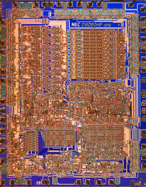
Examination of integrated circuits with reflected light can serve many purposes. For instance, details of a particular circuit structure such as register areas, data busses, memory storage, and logic units are readily apparent (see Figure 3). Also, by observing differences in the architecture of various integrated circuits, students can begin to get a handle on the complex electronics involved in modern devices such as radio, television, and computers. Figure 3 illustrates a Nippon Electric Company (NEC) copy of the famous Intel 8080 microprocessor introduced in 1974 as the first stand-alone microprocessor.
|
Reflected differential interference contrast photomicrographs of the 8080 microprocessor. This 8-bit data engine, powered by 6000 transistors, was introduced by Intel in 1974 as the first stand alone microprocessor for personal computers. Data busses and registers, which are clearly delineated in the micrographs, can load and execute byte-sized commands in the processors' 16 kilobit internal memory. The photomicrograph was taken with a Nikon prototype 2.5x DIC objective and with Fujichrome 64T transparency film. |
The introduction of this revolutionary microprocessor was a key factor in the early growth of a fledgling personal computer industry. Figure 3 illustrates the integrated circuit photographed with color transparency film. Notice the advantage of color photomicrography with respect to differentiation of various areas on the integrated circuit. The presence of different hues and shades of color allows the eye to register more details of the integrated circuit even though both photomicrographs are of comparable resolution. This consequence can be equated to the use of color graphics monitors on modern computers where color-coordinated screens have a more pleasing and restful effect on viewers than do monochrome screens with varying grey scales.
As described above, the biological stereo microscope can be very useful in the examination of surface detail on integrated circuits. This is especially true of the larger microprocessors that may exceed 1 cm2 in area. By adding color filtration to the light sources for reflected light microscopy of integrated circuits, one may acquire colored highlighting effects that enhance the appearance of integrated circuits in photomicrographs. It is interesting to experiment with several light sources each with a different color filter. Quite a number of special highlighting effects can be obtained in this manner. Reflected light microscopy has become an indispensable tool for the semiconductor industry due to its usefulness in characterizing manufacturing defects and monitoring the successive stages of integrated circuit fabrication.
|
Reflected differential interference contrast photomicrograph of a high-temperature superconducting crystal of the ceramic, Bi2Sr2CaCu2Ox. |
The phenomena of superconductivity has dominated physics and the materials sciences since the recent discovery of new ceramics that superconduct at liquid nitrogen temperatures [14]. Several of the newer ceramic superconductors are commercially available [15]. These samples can serve a dual purpose in the classroom as a demonstration of the superconductivity effect and as candidates for reflected light photomicrography. Experiments of this type will give students an exciting preview of this important field.
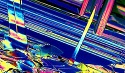
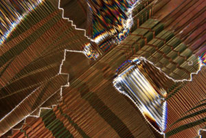
The prism-like color spectrum pictured in Figure 4 arises from crystalline thickness gradients on the surface of a synthetic high-temperature superconducting crystal (Bi2Sr2CaCu2Ox) platelet. This reflected light photomicrograph yields information about the surface topography of the superconductor and helps to provide investigators with an insight into the marvels of superconductivity. Figure 5 is a transmitted light photomicrograph of a lanthanum aluminate (LaAlO3) wafer. The wafer was cut and polished, from a slowly grown 5 cm diameter single crystal, to serve as a substrate for the deposition of superconductor thin-films. These are only several examples of the numerous types of samples that can be imaged and photographed with reflected light microscopy.
|
Transmitted polarized light micrograph of a lanthanum aluminate (LaAlO3) wafer. |
PHOTOMICROGRAPHY
A necessary responsibility of microscopy is to capture the images seen in the microscope onto photographic film to obtain "hard copy" for research records. In a high school environment, classical photography assignments can be coupled with science microscopy studies to provide a multidisciplinary program in photomicrography.
Photomicrography encompasses the techniques of both black and white and color photography. Black and white film processing is substantially lower in cost that color film, if processing is done in-house. Unfortunately, many commercial film processors no longer offer black and white processing services or charge exorbitant amounts for this service. If budget restrictions force the exclusive use of black and white photomicrography, it is advisable to invest in darkroom equipment so students can develop and print their own photomicrographs.
A green gelatin or interference filter should be inserted into the microscope lightpath between the light source and the first polarizer (see Figure 1) for black and white photomicrography. With built-in illumination, the filter can be placed on the field lens prior to the placing of the polarizer. On microscopes that use an external light source, the filter can be taped below the polarizer on the substage condenser.
I recommend the use of Kodak Technical pan film (or it's equivalent) with HC-110 developer for crisp images with excellent contrast and resolution. This film provides intricate detail imaging and reduces the continuous tonal tendencies of the popular black and white films. Printing can be done on Kodak Polycontrast (or again, it's equivalent) paper with Dektol developer. After processing a roll of film, carefully cut the negatives into sections of 5 frames each and store in specially made polyethylene storage sheets. Contact prints can be made by placing a sheet of negatives directly onto an 8" x 10" piece of Polycontrast paper and exposing for a few seconds with the enlarger lens aperture opened to the widest f-stop. Contact sheets are an ideal way of cataloging data and they provide a compact method for storing or sorting through many images. When an enlargement is needed, simply remove the appropriate negative strip from the protective sheet and print with an enlarger.
Color photomicrography is considerably more complicated than black and white photomicrography because color film emulsions are color balanced for a particular spectrum of light 16. The term color temperature refers to the wavelength spectrum emitted by a particular light source. For instance, films intended to be used outside in ordinary daylight or under fluorescent lighting are balanced during manufacture for a color temperature of 5500 K while films made for indoor tungsten lightbulb use are balanced for a color temperature of 3200 K.
The majority of microscopes use a tungsten-halide bulb as a light source. These types of bulbs emit a wavelength spectrum centered in the 3200 K color temperature region. Therefore, films color balanced for this type of illumination will produce the best results. Using daylight balanced films under tungsten illumination will shift all color tones towards a decidedly yellow cast. Likewise, using tungsten balanced films under daylight illumination will shift color tones towards a bluer cast.
All major film manufacturers have one or several 3200 K films available in 35 mm transparency format. Transparency film is preferable to color negative film for several reasons. Most importantly, all color negative films are color balanced for 5500 K and must be manipulated during printing to avoid the yellow cast mentioned above. Most photo processors cannot or will not produce satisfactory results with photomicrographs on color negative film. Also, the contrast and color saturation in transparency film cannot be equaled by color negative film. Finally, color transparencies are easier to label, store, and catalog and they can be projected at seminars.
With a 20 to 100 watt tungsten-halide bulb in your microscope, exposure times are usually very short and allow the use of slow films such as Ektachrome 50 or Fujichrome 64T. Using slow films reduces the grain size in photomicrographs and leads to higher quality enlargements. If tungsten balanced films are not available, a Kodak 80A or equivalent filter can be inserted into the lightpath between the light source and the first polarizer to allow the use of daylight balanced films with minimal color shift. If this filter is used, exposure times must be increased 1-3 f-steps to allow for a reduction in light intensity. Recently, Polaroid introduced a slow speed (ISO 40) color transparency film, designated Polachrome HC, with high contrast that is ideal for photomicrography. This film produces superb contrast and color saturation and can be user-processed in only 2 minutes with a low cost Polaroid processor.
When photographing new samples or after making changes to the microscope (such as installation of polarizers), the new exposure characteristics should be determined on a test roll of film. Bracket several exposures of the same viewfield at least one and preferably two f-steps over and under previous exposure times. This will assure at least one or several good exposures and will yield exposure time information useful for photomicrography of future samples.
The best film, in my opinion, is Fujichrome 64T, a highly color-saturated E-6 transparency film with excellent contrast. Recently, a new emulsion of this film was introduced that is designed to allow push processing with very little reduction in image quality. Push processing is a method developed to increase contrast (inherently low in photomicrographs) and color saturation. This is done by underexposing the film 1 to 2 f-steps and increasing the process time in the first developer during the E-6 process.
CONCLUSIONS
By introducing polarized light microscopy and photomicrography to high school students, you give them experience with a technique that is becoming a main staple of current scientific and industrial research apparatus. Students will find that their creativity in photomicrography is limited only by the boundaries of their imaginations.
ACKNOWLEDGEMENTS
The author would like to thank the Nikon Instrument Group for providing photomicrography equipment and the FSU Center for Materials Research and Technology for continued support.
REFERENCES
1. Saeva, F. D., "Liquid Crystals: The Fourth State of Matter", 2nd Edition (Marcel Dekker, 1979)491 pages.
2. Feldman, L. C., "Fundamentals of Surface and Thin Film Analysis", 2nd Edition, (North-Holland,1986), 352 pages.
3. Davidson, M. W., "Photomicrography of Integrated Circuits", Microscope Technology and News,1990, in press.
4. Silverman, D. A., "Microscapes: The Hidden Art of High Technology", Functional Photography,1987, 22, 24-29.
5. Inoue, S., "Video Microscopy", 1st Edition (Plenum Press, 1986), 584 pages.
6. Pawley, J. B., "Handbook of Biological Confocal Microscopy", (Plenum Press, 1989), 232 pages.
7. Howard, T., "The Nomarski Method", Microscope Technology and News, 1990, 2, 4-6.
8. Delly, J. G., "Photography Through the Microscope", 9th Edition (Eastman Kodak Company, 1988) Chapter 3.
9. Davidson, M. W. "Fascinating Photography With A Simple Light Microscope", PHOTOgraphic Magazine, 1990, in press.
10. Strezlecka, T. E., Davidson, M. W., and Rill, R. L., "Multiple Liquid Crystalline Phases of DNA at High Concentrations", Nature, 1988, 331, 457-460.
11. Livolant, F., Levelut, A. M., Doucet, J., and Benoit, J. P., "The Concentrated DNA Liquid Crystalline Phase is Columnar Hexatic", Nature, 1989, 339, 724-728.
12. Rill, R. L., Livolant, F., Aldrich, H. C., and Davidson, M. W., "Electron Microscopy of Liquid Crystalline DNA: Direct Evidence for Cholesteric-like Organization of DNA in Dinoflagellate Chromosomes", Chromosoma, 1989, 98, 280-286.
13. Van Winkle, D. H., Davidson, M. W., Chen, W-X., and Rill, R. L., "Cholesteric Helical Pitch of Near Persistence Length DNA", Macromolecules, 1990, 23, 4140-4148.
14. Schecter, B., "The Path of no Resistance: The Story of the Revolution in Superconductivity",1st Edition, (Simon and Schuster, 1989), 200 pages.
15. Mims, F. M., "Superconductors", Science Probe!, 1990, 1, 68-74.16. Davidson, M. W. and Rill, R. L., "Photomicrography: Common Ground For Art and Science", Microscopy and Analysis, 1989, May, 7-12.
