
Anatomy of the MIC-D Digital Microscope
Transmitted Brightfield Illumination Mode
Transmitted brightfield illumination is one of the most commonly utilized observation modes in optical microscopy, and is ideal for fixed, stained specimens or other types of samples having high natural absorption of visible light. Collectively, specimens imaged with brightfield illumination are termed amplitude objects because the amplitude or intensity of the illuminating wavefronts is reduced when light passes through the specimen.
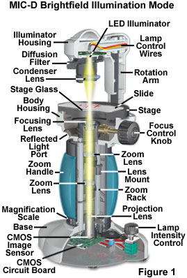
When the illuminator rotation arm of the Olympus MID-D digital microscope is placed in the vertical position (see Figure 1), and the illuminator housing is coaxial with the optical train, the microscope can operate in transmitted brightfield mode. Under these circumstances, the phase relationship between light rays passing through and around the specimen (surround light waves) is such that they are 180 degrees out of phase with light partially absorbed and diffracted by the specimen. This results in destructive interference between the surround and diffracted light at the image plane of the CMOS sensor to produce a visible image with high contrast.
In brightfield illumination, both the light source (a light-emitting diode, or LED, in the case of the MIC-D digital microscope) and condenser are positioned to fill the objective aperture with partially coherent waves that are symmetrical with respect to the microscope optical axis. Because both of the prominent first-order diffraction side bands participate with the surround light waves in formation of the image, the background appears bright, with absorbing structures in the specimen exhibiting a variety of colors and gray-level tones.
The configuration for brightfield illumination with the MIC-D digital microscope is presented in Figure 1. Light waves emitted by the diode (housed in the illuminator) pass through a diffusion filter or screen, and are focused onto the specimen by the condenser lens. After passing through or being diffracted (or absorbed) by the specimen, the waves are collected by the objective and then converged by the zoom optical system and projection lens onto the surface of a CMOS image sensor positioned in the microscope base. The image is focused by translating the objective front and rear lenses with respect to one another, and the overall magnification can be adjusted by rotating the zoom handle. Image information collected by the image sensor is processed and passed to a host computer through the universal serial bus (USB) interface.
The objective numerical aperture specifies the depth of field in brightfield microscopy, and is responsible for determining the size of optical section planes (the thickness of material that is in focus) from the z-axis of the microscope. In brightfield microscopy portions of the specimen that are in focus are often obscured by out-of-focus light originating from planes above and below the plane of focus. This problem is largely circumvented by making very thin sections from the specimen and staining them with tissue-specific dyes or similar reagents to produce a single "layer" only a few microns thick in the z-direction (parallel to the optical axis). The art and science of sectioning and staining biological specimens for observation in brightfield illumination comprises the entire field of histology and medical pathology, although modern fluorescence techniques are rapidly being implemented.
Specimens that alter the intensity of transmitted light are termed amplitude specimens and can be observed in the microscope as a consequence of their ability to absorb or otherwise affect the light intensity, which is proportional to the square of the light wave amplitude. In contrast, transparent specimens that do not absorb light, but instead, produce a phase change of light passing through are termed phase specimens. These specimens are invisible or very difficult to image because the human eye is insensitive to changes in the relative phase shifts of visible light waves. Phase changes are primarily due to differences in thickness and refractive index between the specimen and its surrounding medium. A typical example is living tissue culture cells, which appear almost transparent under brightfield illumination.
As discussed above, the absorption of light to produce colors or vary the brightness of a specimen has been the classical method of producing contrast in brightfield microscopy. The term contrast refers to the ability of an individual specimen detail to be distinguished when compared to the background or other adjacent features. Specimen properties that produce changes in brightness or color differences arise from light absorption, reflection, spatial variation in refractive index, scattering, diffraction, and similar optical phenomena. In general, contrast is measured by the relationship between the highest and lowest intensity in an image, and can be described by a simple formula:
where I(b) is the background intensity and I(s) is the intensity of specimen features for which contrast is being investigated. If the specimen intensity is less (darker) than that of the background, contrast is referred to as being positive, while specimens that are lighter than the background display negative contrast. When a specimen modifies the spectral distribution (color) of light passing through, it produces color contrast. This type of contrast is also produced by interference of white light in specimens with closely spaced periodic structures.
Unfortunately, for many specimens that are unstained or still living, the contrast is so poor that brightfield microscopy is incapable of rendering the specimens visible, despite the ability of the objective to resolve (or clearly separate) fine detail. These specimens must be imaged with contrast-enhancing techniques, such as oblique illumination, phase contrast, differential interference contrast (DIC), darkfield, Hoffman modulated contrast (HMC), or Rheinberg illumination. However, a wide spectrum of specimens, both living and fixed, have sufficient contrast, either with or without dyes and stains, that enable the microscopist to obtain accurate images with brightfield illumination.
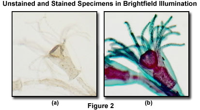
Illustrated in Figure 2 is an unstained (Figure 2(a)) and stained (Figure 2(b)) specimen of the marine organism Obelia, imaged in the MIC-D digital microscope using brightfield illumination. Requiring two separate generations to complete the lifecycle, the first generation of Obelia lives in hydroid colonies, consisting of polyps. The polyps are stalk-like forms (as illustrated in the figure) that attach to a surface (usually the ocean bottom) by means of root-like filaments. This comparison is a vivid demonstration of the dramatic difference in contrast observed between amplitude specimens, which have been stained, and those having very little absorption, rendering them almost transparent in brightfield illumination.
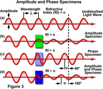
The effect of illuminating light rays by amplitude and phase specimens is presented in Figure 3. The uppermost sine wave in the figure illustrates a typical undisturbed (surround) light wave that does not pass through the specimen. The amplitude and wavelength of the undisturbed light wave passing only through the specimen mounting medium (having refractive index = n) are indicated in the illustration (Figure 3(a)). When light waves enter a stained specimen (represented by the green box in Figure 3(b)) having the same refractive index as the surrounding medium, the waves experience a reduction in amplitude as a result of absorption by the stain, but their relative phase remains unchanged. However, when light waves enter a specimen having a refractive index that is different from the surrounding medium (Figure 3(c)), the amplitude is not affected, but the phase is retarded by approximately 90 degrees. In reality, a majority of the specimens encountered exhibit a combination of amplitude and phase effects (Figure 3(d)), producing changes to both the amplitude and phase (a 180-degree retardation) relationships between the incident and emerging light waves.
Brightfield Illumination Strategies
When brightfield illumination is optimized, the specimen should appear bright and glare-free, with an evenly dispersed background in the field of view. Among the requirements for proper illumination in the microscope is that the diameter of the illuminated area of the specimen plane must be at least as large as that of the field of view observed through the microscope. In addition, the illumination numerical aperture must be variable, but uniform throughout the field of view, ranging from a maximum that is equal to that of the objective, to a minimum that depends on the optical characteristics of the specimen. Finally, the illumination must be of uniform intensity throughout the field of view.
There are several strategies that have been devised over the past 300 years to illuminate microscopes, but the primary method utilized by a majority of the manufacturers involves the principles suggested by Dr. August Köhler in 1893. Köhler illumination operates by focusing the light source in the front focal plane of the condenser and controlling the coherency and spatial distribution of light through two adjustable apertures, termed the field and condenser diaphragms. This method establishes two series of conjugates planes, one set for focusing the illuminating light waves, and the other set for interference of the light waves contributing to image formation.
In Köhler illumination, light is directed through the optical pathway of the microscope and focused with a series of diaphragms, mirrors, beamsplitters, and lenses as it travels from the source to illuminate the specimen and then into the eyepieces or camera system. The lamp collector lens performs in a manner similar to an objective to form a real, magnified image of the light source in the lower (front) focal plane of the substage condenser, which also forms a virtual image of the light source at infinity. Light waves emerging from the condenser pass through the exit pupil of the illumination system, and the specimen is placed in the plane corresponding to the focal point of this exit pupil. The condenser also forms a real image of the field diaphragm in the plane of the exit pupil, which acts as a field stop. By opening or closing the aperture of the field diaphragm, the diameter of the illuminated area can be adjusted, but the illumination intensity remains unchanged. In contrast, the condenser diaphragm regulates the numerical aperture, but not the intensity of illumination. Light waves focused by the lamp collector lens converge into a focal point in the plane of the condenser aperture and emerge as a parallel bundle of rays that illuminate the entire field of the exit pupil.
Modern microscopes utilize tungsten-halogen lamps as light sources for brightfield and other common forms of illumination, and depend upon careful positioning of the lamp filament with respect to the other optical components and diaphragms. Tungsten-halogen lamps emit a continuous spectrum of light centered at 3200 K, which is then passed through a collector and field lens before entering the microscope substage condenser. These lamps are relatively low in cost and have a very long life span, making them excellent candidates for a universal illumination source in brightfield and related forms of optical microscopy.
Recent developments in light-emitting diode technology have yielded light sources that provide intense illumination with a relatively well-balanced spectrum throughout the visible spectral region. In addition, the semiconductor-based lamps have extended lifetimes averaging almost 100,000 hours without significant changes in the spectral output. These properties, coupled to the relative low power consumption, make light-emitting diodes a good candidate for medium intensity (3 to 5 watts) microscopy illumination sources. Light emitting diodes are inherently monochromatic devices, with the color being determined by the bandgap of the semiconductor utilized in the construction. White light LEDs are made from gallium nitride blue-emitting LEDs having the surface of the semiconductor die coated with phosphor, which emits a broad range of visible wavelengths when excited by the blue LED light. Microscopes connected to computers powered through a universal serial bus interface can utilize the LED as a small, low-heat, low power, and low-cost internal light source for imaging and digital capture. The MIC-D digital microscope contains an internal, high-intensity white light-emitting diode that serves as its primary light source and simulates a collector lens.
| Interactive Tutorial | |||||||||||
|
|||||||||||
In order to simplify and reduce the size of the illumination system, the MIC-D digital microscope lacks the condenser and field diaphragm apertures necessary to establish Köhler illumination. Therefore, the microscope must rely on an alternative configuration that does not require these aperture diaphragms to achieve uniform illumination of the specimen in order to fill the objective aperture. Olympus engineers chose the critical (often termed source focused or Nelsonian) method of illumination for the MIC-D, which was first developed by British microscopist Edward Nelson using optical principals advanced by Ernst Abbe. Critical illumination was successfully employed by microscopists from the latter part of the nineteenth century until well into the twentieth century. Even today, there are still some advocates of critical illumination who continue to use the method with microscopes requiring external light sources, or cheaper student microscopes where photomicrography or digital imaging is not an issue.
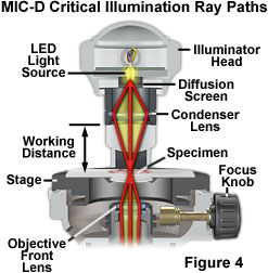
Critical illumination in the MIC-D digital microscope relies on using the condenser lens in the illumination head to produce a focused, real image of the light source (the LED) in the plane of the specimen to achieve a uniform illumination distribution over the entire viewfield (illustrated in Figure 4). Homogeneity of the light source is the important aspect when considering this method of illumination. Prior to the invention of electric lamps, microscopists were limited in their choice of suitable sources for microscope illumination. During daylight hours, they could point their microscopes (or substage reflector mirrors) towards the sky and use the clouds as a crude diffusion screen to spread illumination evenly across the entire field of view. Indoor and night work forced early microscopists to rely on artificial sources of illumination, such as oil lamps. The flame produced by a burning lamp is fairly even and consistent, but other sources, including frosted enlarger bulbs, opal bulbs, ribbon filaments, and light-emitting diodes can also be utilized for critical illumination.
In order to align a microscope for critical illumination, light emitted from the source must be focused by the substage condenser so that a real image of the source is produced in the specimen plane at the microscope slide (Figure 4). The illumination numerical aperture must match that of the objective to ensure that the specimen assumes the optical properties of self-luminosity. In practice, it is often difficult (or impossible) to find focus in the central portion of diffuse light sources (such as a flame or the epoxy jacket of a light-emitting diode), so the "edge" of the source is usually focused with subsequent readjustment of the substage mirror so that the image of the central portion of the light source fills the field of view. In the MIC-D digital microscope, the LED light source is fixed into position with respect to the specimen, and is pre-adjusted at the factory. The amount of light entering the microscope is controlled by adjusting the intensity of the LED through the potentiometer on the base of the microscope or by sliding the diffusion screen into or out of the light path. Enough light must enter the microscope to completely fill the rear focal plane of the objective, and this can be controlled by increasing voltage using the LED intensity potentiometer after inserting the diffusion screen into the optical pathway.
Focusing the light source in the specimen plane is precarious and can often yield a grainy, uneven, or speckled background unless the diffusion screen is inserted into the light path. On compound microscopes, the same effect can be produced by slightly defocusing the substage condenser to produce a more uniform background, but in these instruments, critical illumination has largely been supplanted by the far more efficient Köhler method of microscope illumination. In brightfield microscopy (as well as all other forms), efficient sample illumination is very dependent upon proper alignment of all the optical components of the microscope, including the illumination source. Uneven illumination can have a serious impact on the quality of digital images, causing hot spots, vignetting, color fringes, poor contrast, and a variety of other undesirable effects. Because the MIC-D digital microscope is equipped with a pre-centered lamp (that does not allow for adjustment), the only variables in illumination are the presence or absence of the diffusion screen and the voltage supplied to the light-emitting diode.
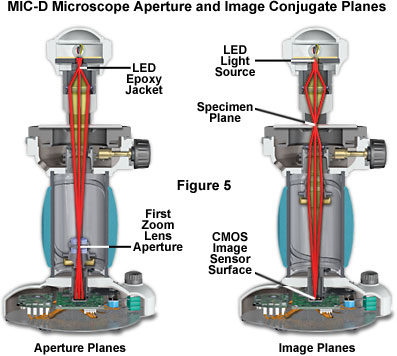
In critical illumination, the light source forms an image on the specimen, which resides in an image (or field) plane. There are three primary image planes in the MIC-D digital microscope (see Figure 5), the LED light source, the specimen plane, and the surface plane of the CMOS image sensor. Each of these planes forms a focused conjugate image of the specimen. The first lens of the zoom optical system is actually the final objective lens, and is seated in a counter-weighted translatable mount that glides up and down the body tube of the microscope as the magnification is varied. An aperture diaphragm built into the mounting seat of this lens element acts as a primary conjugate plane for the illuminating (aperture) light flux passing through the microscope. The second lens of the zoom system performs the function of a relay lens to assist the projection lens in forming a focused image of the specimen on the surface of the CMOS image sensor. A second conjugate aperture plane is situated between the LED and the diffusion screen (Figure 5). Thus, the MIC-D microscope has three principal image conjugate planes and two aperture (or illumination) conjugate planes. The location of these planes differs from those found in conventional microscopes that operate under the principles of Köhler illumination, but they work in combination to perform similar functions.
The MIC-D digital microscope features an inverted design that behaves in a manner similar to a stereo microscope or a very low magnification compound microscope having the condenser top lens removed. In this configuration, the field diaphragm of a compound microscope (but not present in the MIC-D) no longer acts as a light stop to reduce glare, which is already limited by the fact that light rays passing through the specimen plane enter the objective at very low angles of inclination. The low angle of divergence from the light cone entering the objective reduces image defects (aberration) and leads to a simpler design of the lens system. In addition, the aperture of a low power objective is not in the real focal plane, but is placed very close to the last lens element (the first lens in the MIC-D microscope zoom system). Although the illumination head of the MIC-D digital microscope lacks diaphragms, the narrow diameter of the diffusion screen serves as an aperture for the illumination system, forming a real image at a finite distance from the light source.
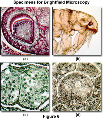
The long working distance and inverted design of the MIC-D condenser system (24 millimeters) enables the microscope to be employed to examine living organisms, such as cells in tissue culture vessels or microscopic pond creatures. In addition, the design can also be utilized for in vitro fertilization studies or elementary patch clamp experiments. As discussed above, a wide spectrum of amplitude specimens can be successfully imaged in the MIC-D microscope under brightfield illumination. Several examples are presented in Figure 6, which represent typical specimens commonly examined in an educational setting.
Presented in Figure 6(a) is a stained thin section of tooth enamel formation from an immature pig. Visible in the image are the epithelial cells, including ameloblasts, which produce enamel matrix proteins. This digital image displays excellent contrast and color saturation, as would be expected from a brightfield microscope under conditions of proper alignment and illumination. Unstained insects, ticks, worms, and other small creatures often provide excellent specimens for imaging in brightfield microscopy due to the inherent contrast produced by the chitin pigments residing in the exoskeleton. Figure 6(b) illustrates a common flea (from the genus Ctenocephalides) under brightfield illumination. The image reveals many of the intricate anatomical details present in this tiny parasite, such as the whiskers, eyes, mouthparts, and legs. Other insects, when properly mounted, produce equivalent images.
Thin sections of multiply stained plant tissues are also good candidates for imaging under brightfield illumination conditions. The digital image presented in Figure 6(c) is a stained thin section of pine staminate cone tissue, revealing an array of winged pollen grains within the fertile reproductive organ. Other plant tissues often exhibit considerably more color and contrast through the application of absorbing chemical stains. The fossil thin section illustrated in Figure 6(d) is from a cephalopod having a goniatitic suture morphology, and displays good contrast, although these types of specimens usually are not prone to an elaborate array of color. In general, many of the stained thin sections available for sale from science supply houses are good candidates for imaging with brightfield microscopy.
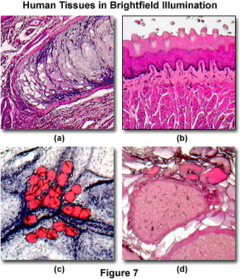
In addition to having the capability of imaging many common biological specimens, the MIC-D digital microscope performs well in a medical diagnostic situation requiring analysis of anatomical and pathological specimens. Illustrated in Figure 7(a) is a stained thin section of the human epiglottis, a thin, leaf-shaped flap of tissue that closes the opening into the larynx during swallowing. Numerous fine specimen details are visible in the digital image. Another stained human tissue thin section is illustrated in Figure 7(b). This image is a section of human tongue, which is stained with the Mallory reagent, an important dye used by microscopists and histologists for preparations of connective tissues, fungi and molds, glands, and other tissues, such as skin. These stains often feature alum (or iron) hematoxylin, a natural dye that stains nuclei blue and, when coupled with eosin, stains cytoplasm pink.
Another example of a pathological stain, often applied to human tissue, is illustrated in Figure 7(c). The tissue is human adipose (fat) tissue, a specialized connective tissue that serves as a main storage site for triglycerides, and is found in two forms, brown and white. The digital image illustrated in Figure 7(c) was captured with the MIC-D microscope and reveals fat globules in a thin section of adipose tissue stained with the dye Sudan IV. Finally, a thin section of human corpus luteum stained with eosin and hematoxylin is presented in Figure 7(d). Although this tissue is stained in manner similar to many other human tissues, it displays a somewhat different color spectrum due to differential absorption of the dyes by various portions of the tissue.
In conclusion, brightfield illumination is the most commonly employed observation mode in optical microscopy. A wide variety of specimens, ranging from stained animal and plant tissues to thin sections of minerals, whole specimen mounts, and living creatures have been imaged in brightfield microscopy. Almost every compound and stereo microscope is capable of producing brightfield images at a variety of magnifications, and many new designs, such as the Olympus MIC-D microscope, provide digital imaging capabilities.
Contributing Authors
Michael W. Davidson - National High Magnetic Field Laboratory, 1800 East Paul Dirac Dr., The Florida State University, Tallahassee, Florida, 32310.
BACK TO MIC-D MICROSCOPE ANATOMY
BACK TO THE OLYMPUS MIC-D DIGITAL MICROSCOPE
Questions or comments? Send us an email.
© 1995-2025 by Michael W. Davidson and The Florida State University. All Rights Reserved. No images, graphics, software, scripts, or applets may be reproduced or used in any manner without permission from the copyright holders. Use of this website means you agree to all of the Legal Terms and Conditions set forth by the owners.
This website is maintained by our
Graphics & Web Programming Team
in collaboration with Optical Microscopy at the
National High Magnetic Field Laboratory.
Last Modification Tuesday, Sep 11, 2018 at 03:50 PM
Access Count Since September 17, 2002: 31972
Visit the website of our partner in introductory microscopy education:
|
|