
Advanced Condenser Systems
High-Performance Condensers
The Intel Play QX3 Computer Microscope is capable of imaging specimens using either transmitted or reflected brightfield illumination. In transmitted light mode, a small tungsten lamp positioned within a mixing chamber beneath the stage provides the source of illumination. Light emitted from this lamp is mixed within the confines of the mixing chamber and is then directed through a frosted plastic diffusion screen to illuminate a specimen placed on the microscope stage.
There are several problems associated with using this type of illumination for transmitted optical microscopy. The most serious drawback is a lack of organization of the illuminating light rays as they pass through the specimen. Light emitted from the QX3 stage diffusion screen travels upward in the direction of the objective front lens, but it is also reflected, scattered, and diffracted by the screen into a large number of point light sources, which hampers the ability to achieve illumination of consistent numerical aperture.
More advanced optical microscopes are equipped with a substage condenser that gathers light from the microscope light source and concentrates it into an organized cone of light, which illuminates the specimen with uniform intensity over the entire objective rear focal plane. It is critical that the condenser light cone be properly adjusted to optimize the intensity and angle of light entering the objective front lens. Each time one of the microscope objectives is changed, a corresponding adjustment must be performed on the substage condenser aperture diaphragm to adjust the numerical aperture of the illuminating cone of light to match that of the new objective.
| Interactive Java Tutorial | |||||||||||
|
|||||||||||
Performance of the QX3 microscope can be dramatically enhanced by the addition of a substage condenser to the optical pathway. It would be difficult to build a condenser into the plastic microscope stage due to space limitations, but the microscope body is readily adaptable to an optical bench or similar framework that will allow positioning of a condenser in the light path.
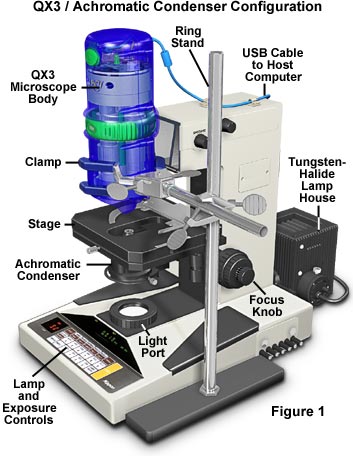
The microscope configuration illustrated in Figure 1 has been designed to test the quality of digital images produced with the QX3 microscope optical components and digital imaging system when assisted by an advanced substage condenser. This configuration employs a Nikon Microphot SA stand with an internal tungsten-halide light source and achromatic substage condenser in place of the QX3 stand with its tungsten bulb and mixing chamber. Removal of the Nikon microscope nosepiece housing was necessary in order to obtain room for mounting the QX3 body directly above the substage condenser in the center of the optical pathway. A ring stand with a three-fingered clamp is used to secure the QX3 body in place. Alignment of the microscope body with the condenser is accomplished by placing a stage micrometer on the mechanical stage and adjusting the clamp position until the micrometer is in sharp focus throughout the viewfield.
The configuration (Figure 1) takes advantage of the movable mechanical stage that can be moved up and down to achieve proper focus, and translated in the X- and Y- directions to allow controlled scanning of the entire specimen. The setup also allows utilization of the built-in tungsten-halide illuminator and field diaphragm, which enables the microscope to be adjusted for proper Köhler illumination in order to optimize the quality of digital images.
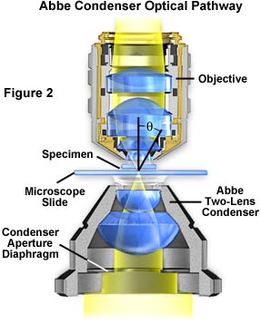
A simple two-lens Abbe condenser installed in a typical microscope optical pathway is illustrated in Figure 2. Light from the microscope illumination source (the lamphouse) passes through the condenser aperture diaphragm located at the base of the condenser, and is concentrated by internal lens elements, which then project light through the specimen in parallel bundles from every azimuth. The size and numerical aperture of the light cone is determined by the opening size of the aperture diaphragm, and can be easily changed with a lever or knurled collar that adjusts the size of the diaphragm. After passing through the specimen, the light diverges to form an inverted cone of illumination with the proper angle (the angular aperture, or 2q, as illustrated in Figure 2) to fill the entire front lens of the objective.
| Interactive Java Tutorial | |||||||||||
|
|||||||||||
Aperture diaphragm size adjustment and proper focusing of the condenser are of critical importance in realizing the full potential of the objective. Specifically, appropriate use of the adjustable aperture iris diaphragm (incorporated into the condenser or just below it) is very important in securing correct illumination, contrast, and depth of field. The opening and closing of this iris diaphragm controls the angle of illuminating rays (and thus the aperture) that pass through the condenser, through the specimen and then into the objective. Condenser height is controlled by a rack and pinion gear system that allows the condenser focus to be adjusted for proper illumination of the specimen.
Correct positioning of the condenser with respect to the cone of illumination and focus is critical to quantitative microscopy and optimum digital imaging or photomicrography. Care must be taken to guarantee that the condenser aperture is opened to the correct position in order for the inverted light cone to match the objective numerical aperture. When the condenser aperture diaphragm is opened too wide, stray light generated by refraction of oblique light rays from the specimen can cause glare and lower the overall contrast. On the other hand, when the aperture diaphragm is made too small, the illumination cone becomes insufficient to provide adequate resolution and the image is distorted due to refraction and diffraction artifacts from specimen details.
The simplest and least corrected condenser is the Abbe condenser (Figure 2), which has only two optical lens elements. This condenser produces an image of the illuminated field diaphragm that is not sharp and is surrounded by blue and red color at the edges. As a result of minimal optical correction, the Abbe condenser is suited mainly for routine observation with objectives of modest numerical aperture and magnification. These qualities make the Abbe condenser ideal for adaptation to the QX3 microscope body to produce a more sophisticated optical train.
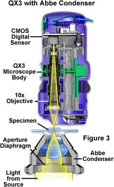
A schematic configuration illustrating the adaptation of an Abbe condenser to the QX3 microscope body is presented in Figure 3. Light from the source is focused onto the specimen plane where some is absorbed or passes through undeviated, while the rest is refracted and diffracted into the inverted cone of illumination that enters the QX3 objective front lens. The condenser aperture diaphragm can be adjusted to maximize the light cone in order to take advantage of the objective's numerical aperture in the same manner as discussed above. Digital images obtained using the QX3 microscope body with and without a substage condenser at the microscope's highest magnification (200x) are illustrated in Figure 4. Note the dramatic improvement in image contrast, resolution, and overall sharpness when a Nikon substage condenser is used to organize the cone of illumination entering the objective front lens.
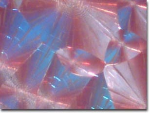
Birefringent Biotin (Vitamin H) Crystallites
 |
|
(a) QX3 with mixing chamber (stock configuration with 200x objective) |
 |
| (b) QX3 with achromatic condenser (imaged with the 200x objective) |
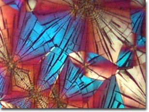
The specimen in Figure 4 is a thin preparation of vitamin H (biotin) crystallites examined with polarized light and a full-wave retardation plate added to the optical pathway. Under these conditions, light is first polarized before it enters the substage condenser and passes through the specimen. The double-refracting nature of birefringent biotin crystallites splits the plane-polarized light (as it passes through the specimen) into an ordinary and extraordinary set of light rays that have polarization vectors perpendicular to one another. After exiting the specimen, the light is further retarded by the full-wave plate, which is positioned between the specimen and the analyzer (the second polarizer). Finally, the polarized light is "recombined" in the analyzer and is captured by the QX3 microscope's CMOS digital image sensor, yielding the beautiful display of color caused by interference of phase-shifted light wave vector components passing through the analyzer.
The digital image presented in Figure 4(a) illustrates a viewfield taken from a stock QX3 microscope modified for crossed polarized illumination with a full-wave retardation plate. Note the general lack of specimen detail and the overall poor image contrast throughout the viewfield. This situation is typical of that observed with transmitted light microscopy when the condenser is absent or severely mis-configured. Adding a substage condenser to the optical pathway results in the digital image shown in Figure 4(b), which is a viewfield almost identical to the one presented in Figure 4(a). It is apparent that specimen contrast, detail and color saturation are greatly improved with the addition of a condenser to the optical pathway. We have found similar improvements using a QX3 microscope configured for brightfield, darkfield, and Rheinberg illumination.
Image Formation
When imaging specimens with the QX3 computer microscope in transmitted mode, light from the tungsten lamp is mixed in the substage mixing chamber and is then directed onto the specimen through the diffusion screen built into the stage. Some of this light passes both around and through the specimen without being disturbed in its path. Undisturbed light is called direct or undeviated light. Background illumination (often called the surround) passing around, but not through, the specimen is also undeviated light.
A portion of light passing through the specimen is deviated when it encounters parts of the specimen. Such deviated light (also called diffracted light) is rendered one-half wavelength or 180 degrees out of step (or more commonly, out of phase) with the direct light that has passed through undeviated. The phase difference of deviated light, caused by the specimen itself, enables this light to cause destructive interference with the direct light when both arrive at the intermediate image plane located between the objective rear focal plane and the CMOS digital sensor. Light captured by the digital imaging chip and associated circuitry is translated into electrical signals that are further magnified by the Intel Play software.
What has happened is that the direct or undeviated light is projected by the objective and spread evenly across the entire intermediate image plane. The light diffracted by the specimen is brought to focus at various localized places on the same image plane, where the diffracted light causes destructive interference and reduces intensity resulting in more or less dark areas. These patterns of light and dark are what we recognize as an image of the specimen. Because our eyes are sensitive to variations in brightness, the image becomes a more or less faithful reconstitution of the original specimen.
To help understand the basic principles of image formation in the microscope, it is helpful to consider a specimen of known structure, such as a stage micrometer or similar line grating having finely ruled dark lines that are closely spaced together. When the line grating is placed on the microscope stage and brought into focus, a series of spots corresponding to diffraction orders is present at the rear focal plane of the objective (see Figure 5). It is impossible to observe these diffraction spectra within the optical path of the QX3 microscope, however the spectra illustrated in Figure 5 simulate what would occur in the microscope at high numerical aperture using a substage condenser.
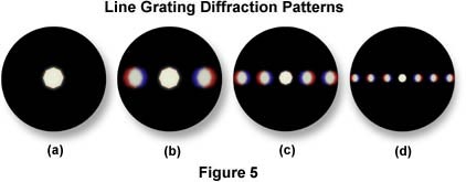
The central spot in the diffraction spectra illustrated in Figure 5 represents undeviated light (also called zeroth order light) passing through the condenser aperture diaphragm when it is closed most of the way. To the right and left of the central spot (Figures 5(b) - 5(d)) are a series of spectra (also images of the aperture diaphragm), each colored blue on the part closest to the central spot and colored red on the part of the spectrum farthest from the central bright spot. The intensity of these colored spectra decreases according to how far the spectrum is from the central spot. Spectra illustrated to the left and right of the central spot in Figure 5(b) represent first order diffraction maxima as seen through a low-power objective at low numerical aperture. As the numerical aperture and magnification of the optical system is increased, additional fainter images of the aperture diaphragm appear on each side of the zeroth order central spot, as illustrated in Figure 5(c) and 5(d). These represent 2nd, 3rd, and 4th (and higher) diffraction orders that have been captured by the objective. This concept is covered in more detail in the discussion on Image Formation in the Molecular Expressions Microscopy Primer.
Microscope specimens can be considered as complex line gratings with details and openings of various sizes. This concept of image formation was developed by Ernst Abbe, the famous German microscopist and optics theoretician of the nineteenth century. According to Abbe, the details of a specimen will be resolved if the objective captures the zeroth order of light and at least the first order (or any two orders, for that matter). The greater the number of diffracted orders that gain admittance to the objective, the more accurately the image will represent the original object. It is obvious, from examining Figure 4(b), that when a substage condenser is present, light emitted from the condenser is more organized and a higher number of diffracted orders are captured from the QX3 objective. The lack of detail and contrast in Figure 4(a) is due to spreading of the diffracted light and the inherently low numerical aperture of the optical system.
Another factor affecting the orders of diffracted light captured by the microscope objective is the refractive index of the imaging medium. The QX3 microscope is designed to operate with air between the specimen and the objective front lens. Higher quality research-grade microscopes often use a medium of higher refractive index, such as immersion oil, to help capture more diffracted orders and yield better resolution images. Moreover, because blue light is diffracted as a lesser angle than green light or red light, a microscope objective lens of given aperture may capture more orders of light when the wavelengths are in the blue region of the visible light spectrum. These two principles are combined to derive the classic Rayleigh equation often cited for optical resolution in the microscope:
Where d is the space between two adjacent particles (still allowing the particles to be perceived as separate), l is the wavelength of illumination, and NA is the numerical aperture of the objective. The greater the number of higher diffracted orders admitted into the objective, the smaller the details of the specimen that can be clearly separated (resolved). Hence the value of using high numerical aperture objectives for best detail resolution and optical clarity for specimens. Note that the Rayleigh equation is highly dependent upon the numerical aperture of the optical system. When a condenser is substituted for the diffusion screen in the QX3 microscope stage, the dramatic increase in resolution is partially due to increased numerical aperture of the entire optical system.
Reducing the number of diffracted orders captured by the objective reduces the resolution of object detail in a specimen, and can destroy resolution altogether when enough diffraction orders are blocked. In a specimen with very minute details, such as the biotin crystallites in Figure 4, the diffraction orders are spread at a very large angle, requiring a high numerical aperture optical system to capture them. This is why much of the detail present in Figure 4(b) is unresolved in Figure 4(a).
Remember that image formation occurs within the microscope objective. It should now be obvious that the quality of image formed in the objective is heavily dependent upon the numerical aperture of the objective/condenser combination, as well as the ability of the condenser to form a distinct cone of illumination that fills the objective front lens. Light emitted by the QX3 diffusion screen, located in the microscope stage, does not form an organized cone of illumination, and this contributes to the lack of image quality observed in the microscope as it is produced in the stock configuration.
The Abbe condenser, discussed above, is one of the simplest condensers available for optical microscopy. Higher levels of condenser optical correction are available, and these are capable of producing higher numerical apertures with greater resolving power and fewer aberrations. The condenser numerical aperture capability should be equal to or slightly less than that of the highest objective numerical aperture. Several condensers of high optical correction are illustrated in Figure 6. The condenser shown in Figure 6(a) is an Abbe condenser that is not corrected optically for either spherical or chromatic aberration (Table 1). A higher level of correction and optical performance is found with the aplanatic condenser illustrated in Figure 6(b). This condenser contains four lens elements, which are collectively corrected for spherical aberration in two wavelengths.
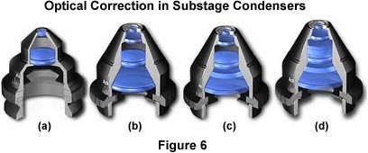
The next highest level of optical correction is found in the achromatic condenser shown in Figure 6(c). Achromatic condensers are corrected for chromatic aberration in two wavelengths. The highest level of correction for optical aberration is incorporated in the aplanatic-achromatic condenser (Figure 6(d)). This condenser is well corrected for both chromatic and spherical aberrations and is the condenser of choice for use in critical color photomicrography with white light.
Condenser Aberration Corrections
|
||||||||||||||||||||
Table 1
It should be obvious from this discussion that attention to organization of the illuminating light rays can dramatically affect image quality with the QX3 microscope. By adapting a simple condenser to the microscope, image quality is greatly enhanced, especially at higher magnifications. More specific examples are described in the section on using an achromatic condenser with the Intel Play QX3 Computer Microscope.
BACK TO ADVANCED CONDENSER SYSTEMS
Questions or comments? Send us an email.
© 1995-2025 by Michael W. Davidson and The Florida State University. All Rights Reserved. No images, graphics, software, scripts, or applets may be reproduced or used in any manner without permission from the copyright holders. Use of this website means you agree to all of the Legal Terms and Conditions set forth by the owners.
This website is maintained by our
Graphics & Web Programming Team
in collaboration with Optical Microscopy at the
National High Magnetic Field Laboratory.
The QX3 microscope design is copyrighted © 2025 by Mattel, Inc. Intel® Play™ is a registered trademark of the Intel Corporation. These companies reserve all of their rights and privileges under copyright law. The material contained in this website is solely the opinion of the authors and is intended for eduational use only.
Last Modification Friday, Nov 13, 2015 at 02:18 PM
Access Count Since April 23, 2000: 22335
Visit the official Intel Play website:
![]()