Microscope Objectives
Image Formation
In the optical microscope, when light from the microscope lamp passes through the condenser and then through the specimen (assuming the specimen is a light absorbing specimen), some of the light passes both around and through the specimen undisturbed in its path. Such light is called direct light or undeviated light. The background light (often called the surround) passing around the specimen is also undeviated light. On the other hand, some of the light passing through the specimen is deviated when it encounters parts of the specimen.
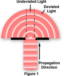
Such deviated light (as you will subsequently learn, called diffracted light) is rendered one-half wavelength or 180 degrees out of step (more commonly, out of phase) with the direct light that has passed through undeviated. The one-half wavelength out of phase caused by the specimen itself enables this light to cause destructive interference with the direct light when both arrive at the intermediate image plane at the diaphragm of the eyepiece. The eye lens of the eyepiece further magnifies this image which finally is projected onto the retina or the camera film.
| Interactive Tutorial | |||||||||||
|
|||||||||||
What has happened is that the direct or undeviated light is projected by the objective and spread evenly across the entire image plane at the diaphragm of the eyepiece. The light diffracted by the specimen is brought to focus at various localized places on the same image plane, as illustrated in Figure 2; and there the diffracted light causes destructive interference, and reduces intensity resulting in more or less dark areas. These patterns of light and dark are what we recognize as an image of the specimen. Since our eyes are sensitive to variations in brightness, the image then becomes a more or less faithful reconstitution of the original specimen.
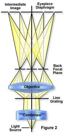
To help you understand the basic principles, it is suggested that you try the following exercise and use as your "specimen" an object of known structure, such as a stage micrometer or similar grating of closely spaced dark lines. To proceed, place the finely ruled grating on the microscope stage and bring it into focus using first a 10X and then the 40X objective. Remove the eyepiece and, in its place, insert a phase telescope so that you can focus on the back focal plane of the objective. If you close down the condenser diaphragm most of the way, you will see a bright white central spot of light which is the image of the aperture diaphragm. To the right and left of the central spot, you will see a series of spectra, each colored blue on the part closest to the central spot and colored red on the part of the spectrum farthest from the central bright spot (as illustrated in Figure 3). The intensity of these colored spectra decreases according to how far the spectrum is from the central spot.
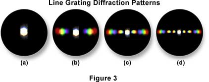
Those spectra nearer the periphery of the objective are dimmer than those to the central spot. This is illustrated in Figure 3 using three different magnifications. In Figure 3(b), the diffraction pattern at the back focal plane of a 10X objective shows two diffraction spectra. If you remove the grating from the stage, as illustrated in Figure 3(a), these spectra disappear and only the central image of the aperture diaphragm remains. If you put back the grating, the spectra reappear. Note that the spaces between the colored spectra appear dark. If you examine the grating with the 10x objective, you will observe that only one pair of spectra can be seen, one to the left of the central spot, one to the right. If you examine the line grating with a 60x objective (as shown in Figure 3(d), assuming it has a higher numerical aperture than your 40x), you will observe more spectra to the right and left than you were able to see with the 40x (Figure 3(c)) in place.
| Interactive Tutorial | |||||||||||
|
|||||||||||
Since the colored spectra disappear when the grating is removed, it can be assumed that it is the specimen itself that is affecting the light passing through, thus producing the colored spectra. Further, if you close down the aperture diaphragm, you will observe that objectives of higher numerical aperture "grasp" more of these colored spectra than do objectives of lower numerical aperture. The crucial importance of these two statements for understanding image formation will become clear in the ensuing paragraphs.
The central spot of light (image of the condenser aperture diaphragm) represents the direct or undeviated light passing through the specimen or around the specimen undisturbed (illustrated in Figure 4(b)). It is called the 0th or zeroth order. The fainter colored images of the aperture diaphragm on each side of the zeroth order are called the 1st, 2nd, 3rd, 4th, etc. orders respectively, as represented by the simulated diffraction pattern in Figure 4(a) that would be observed at the rear focal plane of a 40X objective. All the "captured" orders represent, in this case, the diffraction pattern of the line grating as seen at the back focal plane of the objective.
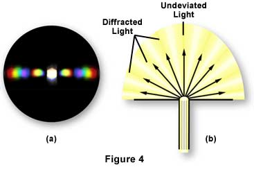
The fainter colored diffracted images of the aperture diaphragm are caused by light deviated or diffracted, spread out in fan shape, at each of the openings of the line grating (Figure 4(b)). The blue wavelengths are diffracted at a lesser angle than the green wavelengths, which are at a lesser angle than the red wavelengths.
At the back focal plane of the objective, the blue wavelengths from each slit interfere constructively to produce the blue area of the diffracted image of each spectrum or order; similarly for the red and green areas (Figure 4(a)). Where the diffracted wavelengths are 1/2 wave out of step for each of these colors, the waves destructively interfere. Hence the dark areas between the spectra or orders. At the position of the zeroth order, all wavelengths from each slit add constructively; this produces the bright white light you see as the zeroth order at the center of the back focal plane of the objective (Figures 3 and 4).
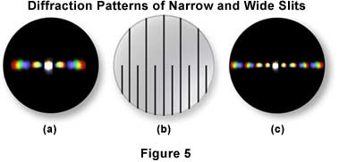
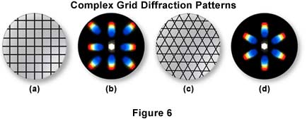
The closer the spacing of a line grating, the fewer the spectra that will be "captured" by a given objective, as illustrated in Figure 5. The diffraction pattern illustrated in Figure 5(a) was captured by a 40x objective imaging the lower portion the line grating in Figure 5(b), where the slits are closer together. In Figure 5(c), the objective is focused on the upper portion of the line grating (Figure 5(b)), and more spectra are captured by the objective. The direct light and the light from the diffracted orders continue on, being focused by the objective, to the intermediate image plane at the diaphragm of the eyepiece. Here the direct and diffracted light rays interfere and are thus reconstituted into the real, inverted image that is "seen" by the eye lens of the eyepiece and further magnified. This is illustrated in Figure 6 with two types of diffraction gratings. The square grid illustrated in Figure 6(a) represents the orthoscopic image of the grid (i.e. the usual specimen image) as seen through the full aperture of the objective, while the diffraction pattern derived from this grid is shown as a conoscopic image that would be seen at the back focal plane of the objective. Likewise, the orthoscopic image of a hexagonally arranged grid (Figure 6(c)) produces a corresponding hexagonally arranged conoscopic image of first order diffraction patterns (Figure 6(d)).
Microscope specimens can be considered as complex gratings with details and openings of various sizes. This concept of image formation was largely developed by Ernst Abbe, the famous German microscopist and optics theoretician of the nineteenth century. According to Abbe (his theories are widely accepted at the present time), the details of a specimen will be resolved, if the objective "captures" the 0th order of the light and at least the 1st order too; or any two orders. The greater the number of diffracted orders that gain admittance to the objective, the more accurately the image will represent the original object.
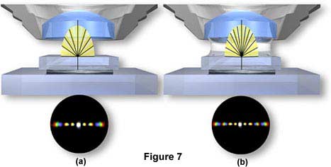
Further, if a medium of higher refractive index than air (such as immersion oil) is used in the space between the front lens of the objective and the top of the coverslip (as shown in Figure 7(a)), the angle of the diffracted orders is reduced and the fans of diffracted light are compressed. As a result, an oil immersion objective can "capture" more diffracted orders and yield better resolution than a dry objective (Figure 7(b)).
| Interactive Tutorial | |||||||||||
|
|||||||||||
Moreover, since blue light is diffracted at a lesser angle than either green light or red light, a lens of a given aperture may capture more orders of light when the light is blue. These two principles explain the classic Rayleigh equation often cited for resolution:
where d is the space between two adjacent particles (still allowing the particles to be perceived as separate),  is the wavelength, and NA is the numerical aperture of the objective.
The greater the number of the higher diffracted orders admitted to the objective, the smaller the details of the specimen that can be clearly separated (resolved). Hence the value of high numerical aperture for such specimens. Likewise, the shorter the wavelength of visible light used, the better the resolution. These ideas explain why high numerical aperture, apochromatic lenses can separate extremely small details in blue light.
If you were to block out the outermost diffracted orders by placing an opaque mask at the rear of the objective, you could reduce the resolution of the lines of the grating, or any other detailed object, or "destroy" the resolution altogether so that the specimen would not be visible. Hence the usual caution not to close down the condenser aperture diaphragm below the suggested 2/3-4/5 of the objective's aperture.
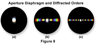
Failure of the objective to "grasp" any of the diffracted orders results in an unresolved image (as shown in Figure 8(a)). Since, in a specimen with very minute details, the diffraction fans are spread at a very large angle, a high numerical aperture objective is needed to "capture" them. Likewise, since the diffraction fans are compressed in immersion oil or in water, objectives designed for such use can give better resolution than dry objectives. Diffraction patterns obtained from objectives of varying resolution are illustrated in Figure 8. The image on the left in Figure 8 has no resolution because there are no higher diffracted orders captured by the objective. The patterns in Figures 8 (b) and (c) show an increasing number of diffracted orders indicating better resolution of the specimen as more orders are grabbed by the objective.
If alternate diffracted orders are blocked out (still assuming the grating as our specimen), the number of lines in grating would appear doubled (a spurious resolution). The important caveat is that actions introduced at the rear aperture of the objective can have significant effect upon the eventual image produced.
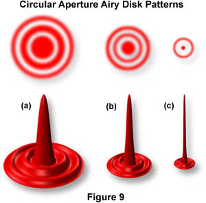
For small details in a specimen (rather than a grating), the objective projects the direct and diffracted light onto the image plane of the eyepiece diaphragm in the form of small, circular diffraction disks known as Airy disks (as illustrated in Figure 9). High numerical aperture objectives "capture" more of the diffracted orders and produce smaller size disks than do low numerical aperture objectives. In Figure 9, Airy disk size is shown steadily decreasing from Figure 9(a) through Figure 9(c). The larger disk sizes in Figures 9 (a) and (b) are produced by objectives with lower numerical aperture, while the very sharp Airy disk in Figure 9(c) is produced by an objective of very high numerical aperture.
| Interactive Tutorial | |||||||||||
|
|||||||||||
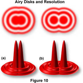
The resulting image at the eyepiece diaphragm level is actually a mosaic of Airy disks which you perceive as light and dark. Where two disks are too close together so that their central black spots overlap considerably, the two details represented by these overlapping disks are not resolved or separated and thus appear as one (illustrated in Figure 10(a)).
The basic principle is that the combination of direct and diffracted light (or the manipulation of direct or diffracted light) is critically important in image formation. The key places for such manipulation are the back focal plane of the objective and the front focal plane of the substage condenser. This principle is fundamental to most of the contrast improvement methods in optical microscopy; it is of particular importance at high magnification of small details close in size to the wavelength of light. Abbe was a pioneer in developing these concepts to explain image formation of absorbing or so-called amplitude specimens. In the 1930's, F. Zernike, a Dutch physicist, extended these principles when he devised and explained phase microscopy.
Contributing Authors
Mortimer Abramowitz - Olympus America, Inc., Two Corporate Center Drive., Melville, New York, 11747.
Michael W. Davidson - National High Magnetic Field Laboratory, 1800 East Paul Dirac Dr., The Florida State University, Tallahassee, Florida, 32310.
BACK TO ANATOMY OF THE MICROSCOPE
