
Interactive Tutorial
MIC-D Zoom Lens System
The MIC-D digital microscope is equipped with a zoom lens system that aids the objective in forming a magnified image of the specimen. Two individual lens elements combine to form the zoom system, and these are translated simultaneously, guided by a track system, within the microscope zoom handle to alter the microscope magnification factor. This interactive tutorial explores the position of the zoom lens elements at various magnification factors.
The tutorial initializes with a cutaway diagram of the MIC-D digital microscope upper and zoom body units, which reveals the objective, internal zoom lens elements, and their mounts. To operate the tutorial, use the Lens Position slider to translate the zoom lens system between the lowest (0.7x) and highest (9.0x) magnification values. As the slider is moved from left to right, the approximate magnification appears above the slider bar. Visitors will note that at the lowest magnification, both zoom lenses are placed near the bottom of the zoom handle, while at the highest magnification, they are positioned near the top of the handle.
The objective magnification and numerical aperture of the MIC-D microscope ranges from 0.7x to 9.0x and 0.05 to 0.17, respectively, as the zoom lens system is racked from the lowest to the highest magnification range. Simultaneously, the viewfield shrinks from 6.9 millimeters at the lowest magnification to 630 micrometers at the highest (assuming a screen dot pitch of 0.3 millimeters). At any point within the zoom range, the magnification can be read directly from the graduated scale at the base of the zoom handle and the optical magnification calculated.
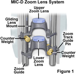
Each of the two zoom lens elements is seated in a specialized cast aluminum mount that enables them to be translated effortlessly on the two guideposts (Figure 1). The front (or upper) zoom lens mount has a larger diameter that enables it to snugly enter the objective boss that is cast into the microscope upper body unit. In addition, the recessed portion of this lens mount allows the lower zoom lens element to fit inside the first mount in order to bring the lenses together for close focusing at both ends of the zoom range. The mounts each contain offset brass counterweights that are designed to stabilize the movement of the lens mounts and eliminate image displacement from the center of the optical train when the zoom handle is rotated (and the lenses are moved up or down).
On the end of the zoom lens mounts that contain the counterweights, a small pin is located that guides each lens mount in one of two grooved tracks inside the zoom handle body. The lens tracks trace a helical pattern within the zoom body and are positioned to produce accurate magnification factors and maintain focus throughout the zoom lens range. Two guideposts serve the dual purpose of maintaining the lens mounts at a stationary angle and securing the upper body unit to the microscope base. The posts are machined from stainless steel bar stock, then drilled and tapped at both ends for screws that attach them to the base and upper body unit. Countersunk holes in the upper body unit and microscope base anchor the guideposts in place. A third stainless steel post stabilizes the microscope and provides a foundation for the shielded wires that provide current for the LED light source. The wires are bound to this post with heat-shrink tubing to keep them from interfering with the moving zoom lens system.
Contributing Authors
Matthew J. Parry-Hill and Michael W. Davidson - National High Magnetic Field Laboratory, 1800 East Paul Dirac Dr., The Florida State University, Tallahassee, Florida, 32310.
BACK TO MIC-D MICROSCOPE ANATOMY
BACK TO THE OLYMPUS MIC-D DIGITAL MICROSCOPE
Questions or comments? Send us an email.
© 1995-2025 by Michael W. Davidson and The Florida State University. All Rights Reserved. No images, graphics, software, scripts, or applets may be reproduced or used in any manner without permission from the copyright holders. Use of this website means you agree to all of the Legal Terms and Conditions set forth by the owners.
This website is maintained by our
Graphics & Web Programming Team
in collaboration with Optical Microscopy at the
National High Magnetic Field Laboratory.
Last Modification Tuesday, Sep 11, 2018 at 03:46 PM
Access Count Since September 17, 2002: 22041
Visit the website of our partner in introductory microscopy education:
|
|