
Digital Image Capture and Processing
Interface Software Image Processing Window
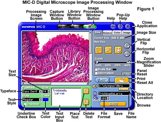
Single images captured by the MIC-D software, or other images saved in the appropriate file formats, can be individually edited with a collection of image processing tools housed in the Image Processing Window. This window includes algorithms for performing operations such as resizing, cropping, rotation, color adjustments, sharpness, brightness, contrast, and gamma correction on digital images displayed in the Processing Image Screen illustrated in Figure 1. Only images selected in the Capture Window or Library Window can be loaded into the MIC-D image processing software.
Images appearing in the Preview Window of the MIC-D software Capture Window can be transported directly into the Image Processing Window by double clicking on the image. Alternatively, if an image appearing in the Thumbnail Group of the Capture Window is selected, it can be imported into the Image Processing Window by clicking on the paint palette icon, positioned as the far right-hand button in the nested group of navigational buttons appearing in the top center section of all three software windows. Likewise, a selected image in the Library Window can be imported into the Image Processing Window by clicking on the same button. Digital video and time-lapse sequences cannot be altered with the MIC-D image processing software, and thus cannot be imported into the processing window.
After an image has been selected and the processing software has launched and initialized, the target image will appear in the Processing Image Screen, occupying a large portion of the upper left-hand section of the processing window (see Figure 1). If the image was captured at a resolution of 640 x 480 pixels, then it will fill the entire window, but smaller images will be positioned at their actual size with the upper left-hand corner of the image constrained to the same corner of the processing screen window. Appearing to the right of the image screen is a tabbed set of four settings panels that control the software image processing functions. When the software initializes, the Size settings panel is displayed by default. Positioned beneath the image screen and the settings panels are the Text Group controls and the Save panel, useful for adding text and saving images, respectively, after they have been processed.
The Size settings panel (illustrated in Figure 2) can be employed to flip, rotate, crop, and zoom images, as well as adding a scale bar and file information to the image. Current image size is displayed in pixels beneath the selection tabs. Images can be cropped by clicking on the Area Select marquee tool button and selecting the rectangular (or square) portion of the image to retain after cropping. When the button is activated and the mouse cursor is placed over the image, the cursor converts into a crosshair to ensure a more accurate selection of specific crop regions. After the region has been selected by dragging the mouse, it is surrounded by a white rectangular box to denote the area that will be retained after cropping. In addition, the selected crop size will be displayed (in pixels) in the New Size text panel located beneath the Current Size panel. To activate the Crop algorithm, click on the Scissors button positioned adjacent to the Area Select button. The cropped image will now move to the upper left-hand portion of the image screen. Cropping the image activates the Reset All button, which turns red to alert the operator to the fact that the image has been modified. Clicking on this button will undo the cropping operation and return the image to its original state. After the image has been resized by cropping and saved, the new (cropped) image size is then displayed in the Current Size text panel.
Images can be magnified with the Zoom tool, which is implemented by a slider that covers a zoom range between 100 and 400 percent of the actual pixel dimensions. This tool is useful for closely examining portions of an image to determine cropping boundaries. When an image has been zoomed, the Crop tool will only operate on the magnified pixel array visualized within the Processing Image Screen. The zoom slider contains a small magnifying glass icon on the left-hand side to indicate smaller zoom sizes, and a large magnifying glass icon on the right-hand size to indicate larger zoom sizes.
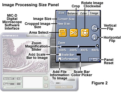
Rotating images is accomplished with the Rotate Image Clockwise button, which contains an icon with an image being encircled by an arrow (see Figure 2). Each time the button is clicked, the image is rotated clockwise by 90 degrees. Clicking on the button four times returns the image to its original position. The Vertical Flip and Horizontal Flip buttons (illustrated in Figure 2) can be utilized to flip the image either vertically or horizontally around the central axis. These buttons can be activated simultaneously to operate in unison by flipping an image both vertically and horizontally. When the image has been flipped, the corresponding control button turns green to alert the operator of the image condition. In addition, the Reset All button turns red. Clicking on the Reset All or Panel Reset buttons will undo rotational and flip changes to an image.
Image information and a magnification scale bar (captured along with the image in the Capture Window and stored in a *.dat file) can be added to the image for documentation purposes in the Size settings panel. The Scale Bar and Information checkboxes are enabled by default when an image is imported into the Image Processing Window. These values are superimposed on the image when it appears in the image screen, but may be removed by deactivating the checkboxes. Information pertaining to the image, including file dimensions (in pixels), the file save date and time, and the filename and directory pathway, are attached to the image when the Information checkbox is enabled. The scale bar, collected along with the image in the Capture Window, can also be attached to and displayed with the image. In order to make these values more visible, a small Color Picker is included adjacent to the Scale Bar checkbox. Clicking inside the Color Picker window will launch a color palette dialog box, which enables the user to choose a color from a pre-selected palette or by defining a new color, for both the scale bar and superimposed text information (the default color is black). The new color should be chosen to be complementary to background image colors for greatest visibility. Saving the image with information and the scale bar attached will permanently embed these variables into the image's pixel array.
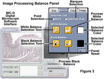
The image processing Balance settings panel, activated by clicking on the Balance tab (see Figure 3), is utilized to set the White and Black balance points on digital images. The Selection Tool palette contains radio buttons for either point or area selection of regions used as reference points for balance corrections. The Point selection tool is selected by default, and can be activated by clicking on either the White Balance or Black Balance selection tool buttons, as illustrated in Figure 3.
The White Balance selection tool control panel contains an activation button having an ink pen icon filled with white ink. Clicking on this button enables the operator to select a region in the image to be employed as a reference point for white balance correction. After the button is activated, the cursor converts into a crosshair and can be placed over the appropriate "reference" pixel in the image. The color of the selected pixel will appear in the Selected Balance Color window positioned on the right-hand side of the settings panel. After the reference point is chosen, click on the Process White Balance arrow button (containing a curved white arrow icon) to adjust image white balance. The reference color should be chosen to approximate, as closely as possible, a white background color. The Black Balance selection tool operates in a similar manner. However, the darkest area of the image (closest to black in color) should be chosen as a reference point for black balance correction.
Better results are often achieved by selecting a group of pixels (as opposed to an individual pixel) for white and black balance correction. This can be accomplished with the MIC-D software by enabling the Selection Area radio button for reference selection (illustrated in Figure 3). After the radio button has been activated, click on the appropriate selection tool and drag the cursor crosshair across the image in a rectangular pattern to define a marquee area for balance adjustment. The average pixel color is then displayed in the Selected Color Balance window. Activating the Process button will apply balance corrections to the image. Balance corrections can be reversed, and the image returned to its original state, by clicking on either the Panel Reset or Reset All buttons.
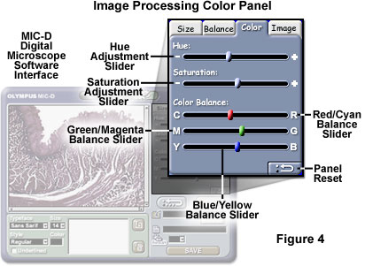
The Color settings panel contains controls to adjusting image hue, saturation, and color balance. This panel can be accessed by clicking on the Color tab in the processing window (as illustrated in Figure 4). To adjust image hue, click and drag the Hue Adjustment slider toward either the right or left boundaries of the value range. Translating the slider to the right will shift the color tones (hues) by adding increasing amounts of red, followed by yellow, and then green. When the slider is moved to the left, color tones shift to purple, blue, and cyan (in that order). In a similar manner, the Saturation Adjustment slider can be translated to the right to increase image saturation, or to the left to decrease saturation. At the far left (extreme) position of this slider control, the image loses all color tones and becomes grayscale.
The Color Balance control group contains three sliders for Red/Cyan, Magenta/Green, and Yellow/Blue balance adjustments. Sliding the Red/Cyan slider to the left increases the intensity of cyan tones, while moving this slider to the right increases the intensity of red tones. Likewise, the Magenta/Green slider increases magenta tone intensity when translated to the left, and green tone intensity when moved to the right. The Yellow/Blue slider also operates in a similar manner. After color balance adjustments have been made, the image can be saved with the same or a new file name, or returned to its original state by clicking on either of the reset buttons (see above).
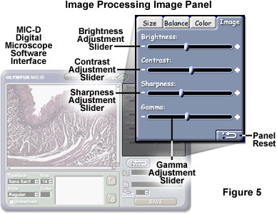
A variety of basic image processing functions are contained in the Image settings panel, including brightness, contrast, sharpness, and gamma correction. Each of these algorithms is controlled by a slider that can be utilized to increase or decrease the value of the target function. For example, the Brightness slider is moved to the left to decrease image brightness and to the right to increase brightness. In a similar manner, the Contrast and Sharpness sliders can be translated to the left and right to decrease or increase the image contrast and sharpness. Translating the Sharpness slider to the left actually introduces a soft blur to image features, while moving the slider to the right applies an edge filter. Gamma corrections (color tone) can also be made to the computer monitor by adjusting the Gamma slider. Image corrections can be reset by clicking on the Panel Reset (or Reset All) button located in the lower right-hand corner of the settings panel.
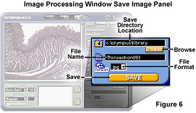
After processing operations are completed, images can be saved in the same or a different file format or under a new name with the Save control panel (see Figure 6). The first step is to type the Windows directory pathway to the target directory into the Save Directory text input box, or use the Browse button to navigate to the directory through the Windows tree listing. Next, type the new file name into the File Name box, and select a format from the File Format pull-down menu (the choices are JPEG, TIFF, and BMP). When all of the parameters have been correctly entered into the Save text input boxes and pull-down menu, click on the Save button to write the image to the host computer hard drive.
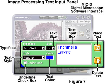
Text can be added to an image using the Text Input settings panel illustrated in Figure 7. Start by typing the appropriate text string in the Text Input Box and selecting a typeface, point size, color, and text style with the pull-down menus positioned adjacent to the text input box. Clicking on either the Typeface, Style, or Size pull down menus will launch a Font dialog box that gives the operator a choice of the currently installed fonts on the host computer. Scroll down the provided lists and choose a typeface, point size, and font style, then click on the OK button to set these parameters. In order to choose a font color other than black, click on the Text Color window to launch a color picker dialog box. Choose from the color palette or specify a custom color and click on the OK button to change the text color. To insert an underline beneath the text placed on the image, activate the Underlined checkbox. Next, click on the Place Text button (positioned to the right of the Text Input Box) and place the mouse cursor, which changes into a crosshair, over a selected region of the image. Click the mouse button to place the text onto the image. To change the position of the text, click on the text and drag the text into a new position.
After being added to an image, text can be edited by clicking on the appropriate text string (to activate the text), which will fill the Text Input Box with the text to be edited. Make the necessary corrections and replace the text on the image. Text can also be removed after being placed on an image by clicking on the text string, then depressing the Delete Text button, located in the lower right-hand corner of the Text control panel (see Figure 7). Note that after saving the image with added text, the text can no longer be edited or deleted.
Located in the right center portion of the Image Processing Window are the Reset All and Print buttons. Any changes made to an image in the Image Processing Window (with the exception of text changes) can be undone by clicking on the Reset All button. Images can be printed by clicking on the Print button, and following the installed printer dialog boxes launched and controlled by the Windows operating system. Regardless of the image size, it will be stretched to fill the entire width of the default paper selected by the printer. In order to avoid highly pixelated images, it is suggested that very small images (less than 300 pixels in length) are not printed for display purposes.
The help and program termination tool group, common to all three program windows (see Figure 1), can be utilized to obtain help or exit the software. Positioned in the upper right-hand corner of the Image Processing Window are three round buttons containing either the word Help, a question mark, and an X symbol. Clicking on the Help button launches the Windows program help files associated with the MIC-D digital microscope hardware and software (the Help button will turn yellow when the mouse cursor rolls over). This program contains a directory tree with information about all aspects of the microscope, including a section dedicated to the Image Processing Window, and should be used for obtaining information about the basic operating procedures and troubleshooting.
The question mark button, which turns green when the mouse cursor rolls over, launches Pop-Up help screens that enable the operator to determine the function of various software features. Clicking on the button changes the cursor into a question mark and arrow pointer, which can then be placed over a button, text box, window, or other area of interest to determine the function. Clicking on the area of interest while the software is in Pop-Up help mode will display a small text dialog box that explains the function of the particular software component.
Clicking on the Close Application button (see Figure 1) will terminate the software interface program instance. When the mouse cursor rolls over this button, it turns red to alert the operator that program termination will commence upon clicking. If images have been captured in the default folder (in the program directory on the system drive) during the software session, the program queries the operator with a message warning that these files will be deleted during the next software session and asks whether the software should be closed. If the operator clicks on the No button in response to this query, the software does not exit. However, if the operator clicks on the Yes button, then the software will terminate without removing the image files from the default directory. During the next software launch instance, a dialog box appears to determine whether the operator wants to delete the files remaining in the default storage directory.
Contributing Authors
Thomas J. Fellers and Michael W. Davidson - National High Magnetic Field Laboratory, 1800 East Paul Dirac Dr., The Florida State University, Tallahassee, Florida, 32310.
BACK TO DIGITAL IMAGE CAPTURE AND PROCESSING
BACK TO THE OLYMPUS MIC-D DIGITAL MICROSCOPE
Questions or comments? Send us an email.
© 1995-2025 by Michael W. Davidson and The Florida State University. All Rights Reserved. No images, graphics, software, scripts, or applets may be reproduced or used in any manner without permission from the copyright holders. Use of this website means you agree to all of the Legal Terms and Conditions set forth by the owners.
This website is maintained by our
Graphics & Web Programming Team
in collaboration with Optical Microscopy at the
National High Magnetic Field Laboratory.
Last Modification Friday, Nov 13, 2015 at 02:19 PM
Access Count Since September 17, 2002: 16380
Visit the website of our partner in introductory microscopy education:
|
|