
Anatomy of the MIC-D Digital Microscope
Oblique Illumination Mode
The true versatility of the unique MIC-D digital microscope design becomes apparent with oblique and darkfield illumination techniques made possible by off-axis translation of the illuminator head and condenser assembly. This feature enables the microscopist to enhance contrast in specimens that would otherwise remain invisible (or nearly so) in brightfield illumination.
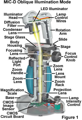
In oblique illumination, direct light from the condenser light cone is restricted to a single azimuth, striking the specimen from only one direction rather than bathing it with an even distribution of light through a well-defined numerical aperture. The net effect is to reveal details in pseudo-relief to produce a shadowed effect on the side opposite the light source and bright specimen highlights on the side nearest the illuminator. In order to achieve oblique or off-axis illumination with the MIC-D digital microscope, the illuminator head is shifted by moving the rotation arm a few degrees away from the upright (brightfield) position. Presented in Figure 1 is a cutaway diagram of the MIC-D microscope revealing many of the internal details, as well as the oblique illumination light path when the illumination head is held stationary, but the rotation arm is shifted 10 degrees off-center.
The useful range of motion for producing oblique illumination with the rotation arm is between 2-3 and 15 degrees from the vertical (optical) axis of the MIC-D digital microscope. In addition, the off-axis angle of specimen illumination can also be modulated or fine-tuned by rotating the illumination head itself (while the arm is held stationary) on a pivot that attaches the head to the rotation arm. The illumination head can be rotated on the pivot to a maximum angle of 10 degrees. Because there are two variables that can be introduced when producing off-axis illumination with the MIC-D, rotation of the main illumination arm and independent rotation of the attached illumination head, the number of possibilities for varying the illumination angle is almost limitless.
| Interactive Tutorial | |||||||||||
|
|||||||||||
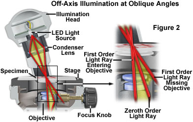
Oblique light rays that illuminate the specimen from a single angle subsequently enter the microscope objective through the front lens element near the edge of the aperture (very close to the lens mount). The focused light rays converge at the objective rear focal plane and are directed through the MIC-D digital microscope zoom optical system to the projection lens, and then onto the surface of the CMOS image sensor positioned on a circuit board in the microscope base. In effect, oblique lighting has caused the zeroth order (direct or undeviated) light rays to be moved to a position just within the periphery of the objective aperture.
A major consequence of oblique illumination is to shift the zeroth order of light passing through the specimen from the center to one peripheral side of the objective front lens element. This shift of the zeroth order to one side enables one or more additional higher orders of the diffracted light to be included at the rear focal plane of the objective and contribute to the formation of the image (see the light ray diagram in Figure 2). However, only diffracted orders on a single side of the zeroth order (often termed sidebands) are admitted to the objective and, because of the obliquity of illumination, diffracted orders on the other side miss the objective altogether. This concept is illustrated in Figure 2 utilizing ray traces (outlined in red) from the direct zeroth order wave and the two sidebands of the first order diffracted waves.
In general, when transparent specimens are illuminated by a parallel bundle of light rays in transmitted brightfield mode with the MIC-D (or any other microscope), the resulting images have poor visibility and lack a significant degree of contrast. This effect occurs because the light diffracted by the specimen is a quarter-wavelength out of phase with the direct (undeviated or surround) light passing through the specimen when both are recombined at the intermediate image plane. However, the diffracted light generated when the specimen is illuminated contains sidebands on either side of the zeroth order undeviated light, which are offset from the quarter wave displacement by a defined margin. If one sideband of the diffracted light is prevented from reaching the image plane, constructive and destructive interference will occur between the remaining sideband and the direct light to produce a visible image at the intermediate image plane of the microscope. Oblique illumination is an excellent mechanism to achieve the sideband suppression necessary for the image formation process.
In Figure 2, the inset depicts a close-up view of three individual light rays that are passed through or diffracted by the specimen. One of the diffracted component sidebands is captured by the objective, along with the direct light passing through the specimen, while the other misses entering the objective front lens element altogether. Interference between the sideband admitted by the objective and the direct light undergoes interference at the image plane to produce an image of the specimen having significantly more contrast and visibility than would be obtained by axial (brightfield) illumination.
Oblique illumination is capable of resolving very fine specimen detail that is difficult to distinguish using conventional brightfield techniques. When oblique light rays strike the objective front lens at angle "ob" to the microscope optical axis, and the refractive index of the medium between the condenser front lens and the objective is n, the relationship between resolution, illuminating wavelength (l), and refractive index can be described as:
Some microscopists equate the term n � sin (ob) with the numerical aperture of illumination, but this is misleading because the equation is not intended to signify a full cone of light emanating from all azimuths, but is restricted to a beam of light produced by off-axis illumination from a single azimuth. In cases where specimen detail is so fine that the zeroth order undiffracted and first order diffracted sideband light are separated by a distance equal to the diameter of the objective aperture, the resolving power is twice as high as observed for axial transmitted illumination and is expressed by the equation:
The optical conditions required for the microscope to conform with the equation above (when utilizing oblique illumination) are such that the fine details of specimen periodicity are limited by the resolving power of the objective. In many cases, specimen details that are resolved utilizing brightfield illumination are so severely lacking in contrast that they can scarcely be visualized or imaged. The net result of observing specimens with oblique illumination is often an increase in resolution (over that obtained in brightfield illumination with a closed condenser aperture diaphragm) and also the production of a shadowed, relief-like pseudo three-dimensional appearance in the image of the specimen.
Oblique illumination techniques are ideal for imaging a wide variety of unstained objects such as living cells, unstained tissues, crystals, diatoms, fossil thin sections, and similar transparent or semi-transparent specimens. However, the resulting images must be viewed and interpreted with caution because the diffracted orders from one side have not contributed to the image formation. Potential false structures appearing in the image can seriously limit the usefulness of oblique light to examine and quantitatively describe previously unobserved specimen detail. This fact should always be taken into consideration when observing specimens with oblique illumination.
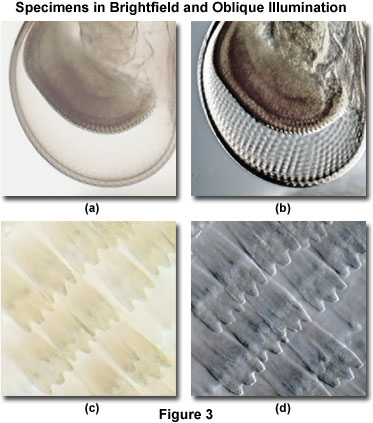
Achieving conditions necessary for oblique illumination, which is a technique that has been employed to enhance specimen visibility since the dawn of microscopy, can be accomplished by simply tilting the rotation arm on the MIC-D digital microscope. Presented in Figure 3 are comparisons between images of specimens acquired in brightfield illumination mode and the same specimens imaged under optimum conditions of oblique illumination. As is obvious from examining the figure, oblique illumination can dramatically increase specimen contrast when compared to conventional brightfield techniques.
The specimen in Figure 3(a) is a brightfield image of a crab megalops developmental stage eyestalk imaged with the MIC-D digital microscope. Individual lens elements in the compound eye are not visible and the stalk suffers from contrast deficiency and lack of significant detail. When the illumination head is tilted approximately 15 degrees from the vertical axis of the microscope, the resulting oblique illumination clearly reveals an array of miniature lenses, as well as structural detail in the stalk. Illustrated in Figure 3(c) are wing scales from the Common Nawab (Polyura athamas) butterfly imaged in brightfield illumination. Individual scales are discernable, but severely lacking in contrast and definition. In oblique illumination (Figure 3(d)), the butterfly wing scales have a quasi three-dimensional appearance that clearly reveals the edges and some surface detail not present in the brightfield image.
| Interactive Tutorial | |||||||||||
|
|||||||||||
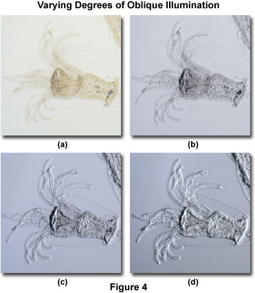
The degree of obliquity can easily be varied through a combination of illuminator and rotation arm tilt angles, as discussed previously. Illustrated in Figure 4 are a series of images captured with the MIC-D digital microscope at varying tilt angles for both the rotation arm and illumination head. The specimen is an unstained whole mount preparation of the Cnidaria (coelenterate) polyp Obelia in the hydroid generation stage. Figure 4(a) reveals the lack of contrast obtained in digital images of this semi-transparent specimen when illuminated in brightfield mode. Note the lack of definition in the tentacles protruding from the mouth and the ectoderm surrounding the cylindrical body.
When the MIC-D digital microscope rotation arm is tilted at a 5-degree angle (Figure 4(b)) from the vertical position, the hydroid specimen acquires more contrast and definition of fine structural detail. Texture becomes slightly visible in the tentacles, although several are still very poorly defined, as is the surrounding ectoderm envelope. Translating the rotation arm to a 10-degree angle increases contrast and the pseudo three-dimensional relief effect, as evidenced by the digital image presented in Figure 4(c). At this position, most of the tentacles have acquired a significant degree of detail and the ectoderm is visible for the first time. Finally, at the maximum tilt angle for oblique illumination (15 degrees; Figure 4(d)), the ectoderm is clearly defined, central regions of the body have more definition, and all of the tentacles display some level of fine detail. From the series of images presented in Figure 4, it is evident that the MIC-D digital microscope has a wide degree of latitude with respect to illumination at oblique angles.
Translating the rotation arm and illuminator off-axis reduces the overall light intensity for specimen illumination. In most cases, when the MIC-D is configured for oblique illumination, the diffusion screen slider should be removed from the optical path to increase the effective light intensity obtained from the light-emitting diode lamp. However, because the diffusion screen acts as a secondary light source to spread illumination more evenly across the field of view, removing this screen can adversely affect the distribution of light reaching the specimen.
If the illumination head is tilted too far off-axis with the diffusion screen removed, chromatic aberration arising from the edge of the condenser lens element is often observed. This is manifested in a rainbow-like spectrum of color appearing adjacent to the illumination border (the transition regions between light and dark portions of the viewfield), and is readily demonstrated at lower magnifications. In order to achieve optimum results with oblique illumination, the specimen image should be evaluated both with and without the diffusion screen. Depending upon specimen thickness and inherent contrast, the quality of digital images can be often increased by leaving the diffusion screen in the optical pathway.
The use of oblique illumination should be restricted to the higher magnification range of the MIC-D digital microscope. At the lowest magnifications, the reduced objective numerical aperture and larger viewfield produce a brightness gradient possessing a sharp border at the edge of the illumination field. The result is a region in the field of view that is brightly illuminated and another region that is much darker (and obscures specimen detail). In practice, the specimen should be positioned and focused in the center of the viewfield at low magnification, and then the magnification increased until the illumination boundary disappears and the background brightness gradient effect is minimized. It is almost impossible to completely eliminate this gradient, although at the highest magnifications, the gradient is barely perceptible.
When compared to the darkfield technique, where the specimen is illuminated from all angles with highly oblique light, asymmetrical oblique illumination produces images whose character is highly dependent upon the incident angle of illumination. Images produced by oblique illumination are asymmetrical in the sense that edges lying perpendicular to the direction of incident illumination are made visible, while those that lie parallel (or close to this direction) are not. This concept is illustrated in Figure 5 for two specimens that exhibit orientational effects in oblique illumination.
Presented in Figure 5(a) is an oblique illumination digital image (captured with the MIC-D microscope) of a ctenoid fish scale, displaying the pattern of "growth rings" that are often utilized to categorize the age of a fish. When the rings are oriented parallel to the direction of off-axis illumination, as they are in Figure 5(a), diamond-shaped patterns of varying sizes are obvious on the scale surface. However, by rotating the specimen by 90 degrees, so that the growth rings are perpendicular to the illumination direction, these patterns are partially masked by the growth ring relief effect and are quite difficult to identify and measure. This specimen clearly demonstrates the dramatic effect observed when viewing specimens in the MIC-D digital microscope at different orientations with respect to the fixed oblique illumination axis.
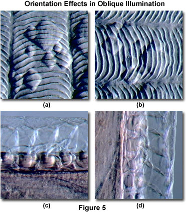
A portion of the dorsal fin structure of the eel-like invertebrate animal known as amphioxus is illustrated in Figure 5(c) and 5(d). Amphioxi have very poorly developed brain and sense organs, and also have no true vertebrae, which may explain their absence from the fossil record. In brightfield illumination, unstained amphioxi exhibit poor contrast and minute details are indiscernible. The orientation of this specimen with respect to the MIC-D illuminator head significantly influences the visibility of details concerning the sub-structure of the fins, as is evident in the figures. When the long axis of the fin is positioned parallel to the illumination source (Figure 5(c)), much of the structure surrounding the thin edge remains difficult to resolve, but details at the base of the fin become highly visible. Re-orientation of the fin perpendicular to the oblique lighting highlights fine structural details not present in the parallel view (Figure 5(d)), and the two orientations can be utilized in combination to reveal anatomical features that might otherwise be overlooked.
The apparent three-dimensional effect afforded by oblique illumination techniques does not represent the actual specimen geometry or topography, and should not be employed to conduct measurements of specimen dimensions. The true value of the oblique illumination image is in revealing transitions in refractive index or other optical path differences within the specimen that enable the morphology and internal structural arrangement to be more clearly understood. The technique can be applied to a variety of materials that appear nearly invisible or transparent in brightfield illumination and cannot be stained or otherwise chemically or thermally treated to enhance contrast. Study of living organisms and processes such as in vitro fertilization, glass or acrylic fibers, chemical crystals, and other unstained materials can be facilitated by the utilization of an easily controlled oblique illumination system.
The optical effects that occur when a microscope objective is illuminated at its margin vary considerably according to lens quality, correction for aberration, and the specimen characteristics. When the illumination beam falls partially outside the objective aperture, as it does in oblique illumination, the result is a reduction of zeroth order light intensity relative to the sideband intensity, and a diffraction pattern is generated at the edge of the objective aperture. For this reason, the illuminating cone should be restricted to less than the full objective aperture to avoid diffraction artifacts (such as interference fringes). Careful experimentation with condenser illumination methodology should ensure an even illumination field at restricted apertures.
Another advantage of using oblique illumination is the ability to perform optical sectioning of transparent specimen with this technique. Sectioning allows the microscopist to focus on a single thin plane of the specimen without interference from confusing images arising in areas above or below the plane that is in focus. The depth of a specimen is measured in a direction parallel to the optical axis of the microscope. Focusing the image establishes the correct specimen-to-image distance, allowing interference of the diffracted waves to occur at a pre-determined plane (the image plane) positioned at a fixed distance from the eyepiece or image sensor. This enables diffracting objects that occur at different depth levels in the specimen to be viewed separately, provided there is sufficient contrast. The entire depth of a specimen can be optically sectioned by sequentially focusing on each succeeding plane. In this system, depth of field is defined as the distance from one level to the next (where imaging of distinct detail occurs), and is controlled by the numerical aperture of the objective.
There are several advantages to oblique illumination when compared to differential interference contrast (DIC) and phase contrast. Birefringence inherent in a specimen does not confuse oblique illumination images, as is the case with DIC, but phase details are clearly observed in directionally shadowed images from the oblique illumination. A good example is vertebrate axons, which are more clearly imaged with oblique illumination due to their highly birefringent myelin sheaths, but create excessive contrast in DIC. In addition, equipment costs are significantly less for oblique illumination than with either DIC, phase contrast, or Hoffman modulated contrast, because the only requirement is a properly configured brightfield microscope. In some cases, oblique illumination techniques enable the microscopist to image deeper into tissue layers than is possible with DIC. Finally, resolution is not compromised over that attainable with brightfield, and contrast can be dramatically enhanced.
Contributing Authors
Thomas J. Fellers and Michael W. Davidson - National High Magnetic Field Laboratory, 1800 East Paul Dirac Dr., The Florida State University, Tallahassee, Florida, 32310.
BACK TO MIC-D MICROSCOPE ANATOMY
BACK TO THE OLYMPUS MIC-D DIGITAL MICROSCOPE
Questions or comments? Send us an email.
© 1995-2025 by Michael W. Davidson and The Florida State University. All Rights Reserved. No images, graphics, software, scripts, or applets may be reproduced or used in any manner without permission from the copyright holders. Use of this website means you agree to all of the Legal Terms and Conditions set forth by the owners.
This website is maintained by our
Graphics & Web Programming Team
in collaboration with Optical Microscopy at the
National High Magnetic Field Laboratory.
Last Modification Tuesday, Sep 11, 2018 at 03:55 PM
Access Count Since September 17, 2002: 17621
Visit the website of our partner in introductory microscopy education:
|
|