
Anatomy of the MIC-D Digital Microscope
Darkfield Illumination Mode
In traditional optical microscopy, darkfield illumination requires blocking the central light that ordinarily passes through and around (surrounding) the specimen, allowing only oblique rays from every azimuth to "strike" the specimen mounted on a microscope slide. When the rotation arm of the MIC-D digital microscope is positioned at a distance greater than 15 degrees from the central (optical) axis, this instrument is capable of imaging specimens by a mechanism that produces results similar to those observed in true darkfield illumination.
Darkfield illumination is often compared with the appearance and visibility of stars on a dark night, which are readily observed despite their enormous distances from the Earth. Stars can be seen because of the stark contrast between their faint light and the black sky. Yet stars are shining both day and night, but are invisible during the day because the overwhelming brightness of the sun obscures the faint light originating from the stars, rendering them invisible. During a total solar eclipse, the Moon moves between the Earth and the sun blocking out the light of the sun, enabling the stars to be seen even though it is daytime. In short, the visibility of faint starlight is significantly enhanced when positioned against a dark background.
This principle is applied in darkfield (also commonly termed darkground) microscopy, a simple and popular method for rendering unstained transparent specimens clearly visible. These specimens often have refractive indices very close in value to that of their surroundings and are difficult to image using conventional brightfield microscopy techniques. For example, many small aquatic organisms, such as those found in stagnant ponds, have a refractive index ranging from 1.2 to 1.4, resulting in a negligible optical difference from the surrounding aqueous medium. These are ideal candidates for darkfield illumination.
| Interactive Tutorial | |||||||||||
|
|||||||||||
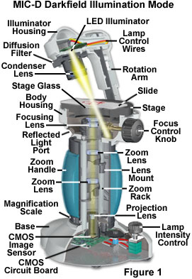
The basic configuration for darkfield illumination with the MIC-D digital microscope is presented in Figure 1. Under normal imaging conditions, the rotation arm is positioned parallel to the optical axis of the microscope to produce brightfield illumination, which is the preferred technique for observing amplitude or stained specimens. Transparent or phase specimens (those having a significant optical path difference from the supporting medium) are difficult to visualize in brightfield mode and benefit from off-axis illumination scenarios, such as oblique and darkfield lighting. Oblique illumination can be achieved by translating (or tilting) the rotation arm and/or the illumination head, in combination, between a range of 2-3 and 15 degrees away from the microscope central vertical axis. If this range is exceeded by a few degrees, the microscope enters a region where the illuminating light rays are highly oblique with regard to the optical axis and the front lens of the objective.
When a specimen is placed under darkfield illumination, especially an unstained, non-light absorbing specimen, the oblique rays cross the specimen and are diffracted, reflected and/or refracted by optical discontinuities (such as the cellular membrane, nucleus, and internal organelles) allowing these faint rays to enter the objective. The specimen can then be seen as a bright highlight on an otherwise black background. In terms of Fourier optics, darkfield illumination removes the zeroth order (unscattered light) from the diffraction pattern formed at the rear focal plane of the objective. This effect results in an image formed exclusively from higher order diffraction intensities scattered by the specimen.
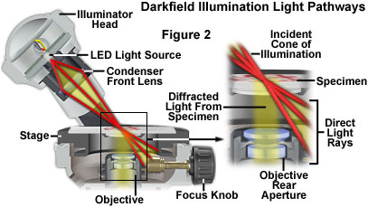
The application of this concept to the Olympus MIC-D digital microscope optical pathway in a darkfield configuration is presented in Figure 2. Light rays emanating in an organized cone of illumination from the off-axis condenser lens are directed across the specimen plane, but enter the stage at a highly oblique angle and miss the objective front lens. However, when the light passes through the specimen, some of the rays are diffracted by the specimen and are able to enter the objective. These light rays are then focused by the optical system of the microscope to form an image on the surface of the CMOS image sensor, which appears as bright specimen highlights on a dark background.
Specimens that have smooth reflective surfaces produce images due, in part, to reflection of light into the objective. In situations where the refractive index is different from the surrounding medium or where refractive index gradients occur (as in the edge of a cellular membrane), light is refracted by the specimen. Both instances of reflection and refraction produce relatively small angular changes in the direction of light, allowing some to enter the objective. In contrast, some light striking the specimen is also diffracted, producing a 180-degree arc of light that passes through the entire numerical aperture range of the objective. The resolving power of the objective is the same in darkfield illumination as observed under brightfield conditions, but the optical character of the image is not as faithfully reproduced (except when a specially-designed iris diaphragm is utilized to lower the effective numerical aperture with high-magnification oil immersion objectives designed specifically for darkfield microscopy).
As in the example of starlight described above, the visibility is greatly enhanced by the contrast between the brightly shining specimen and the dark surrounding background. As discussed above, what has happened in darkfield illumination is that all the ordinarily undeviated rays of the zeroth order have passed by the objective without entering the lens (or have been blocked by an opaque stop in conventional brightfield microscopy). Oblique light rays, now diffracted by the specimen and yielding first, second, and higher diffracted orders at the rear focal plane of the objective, proceed through the optical system to the image plane where they interfere with one another to produce an image of the specimen. In some cases with the MIC-D microscope (depending on the tilt angle of the illumination head), a small portion of the direct light rays may enter the objective at a highly oblique angle. However, these rays will be blocked by the aperture positioned behind the bi-concave secondary objective lens and will not pass directly through the microscope optical system.
Ideal candidates for darkfield illumination include minute living aquatic organisms, diatoms, small insects, bone, fibers, hair, unstained bacteria, yeast, cells in tissue culture, and protozoa. Non-biological specimens include mineral and chemical crystals, colloidal particles, dust-count specimens, and thin sections of polymers and ceramics containing small inclusions, porosity differences, or refractive index gradients. Care should be taken when preparing specimens for darkfield microscopy because features that lie above and below the plane of focus can also scatter light and contribute to image degradation. Specimen thickness and microscope slide thickness are also very important and, in general, a thin specimen is desirable to eliminate the possibility of diffraction artifacts, which can interfere with image formation.
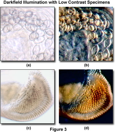
A typical example of two specimens that produce poor contrast in brightfield conditions, but are readily observable under darkfield illumination are presented in Figure 3. The digital image illustrated in Figure 3(a) is a high-magnification brightfield view of the intestinal region in a human whipworm (Trichuris trichiura). Because the specimen is unstained, contrast is reduced and internal anatomical details of the parasite are not discernable. When the rotation arm of the MIC-D is tilted approximately 20 degrees from the vertical position, the whipworm intestinal cavity becomes much better resolved (Figure 3(b)), revealing features that were not apparent in the brightfield view.
A similar situation exists with thicker specimens, such as the crab megalops developmental stage eyestalk shown in Figures 3(c) and 3(d). Although the miniature periodic structures contained in the eye are clearly visible under brightfield illumination (Figure 3(c)), they are dramatically enhanced, both in clarity and contrast, under darkfield conditions (Figure 3(d)). Both of the specimens illustrated in Figure 3 are relatively thick specimens when compared to thin tissue sections, small aquatic organisms, or bacteria. In fact, because darkfield illumination with the MIC-D digital microscope is limited to a single azimuth, thick specimens perform much better and produce superior images than do relatively thin specimens with this microscope. This observation is in direct contrast to the results obtained with traditional compound microscopes, which operate at high numerical apertures with specialized darkfield condensers. The primary reason for the discrepancy between the two microscope configurations is the low objective numerical aperture range for the MIC-D, coupled to the limited directional lighting available from a single LED source positioned at a highly oblique angle. Thinner specimens can be imaged with greater efficiency in the MIC-D microscope when auxiliary illuminators, such as a tungsten-halogen source coupled to a fiber optic light pipe, are obliquely positioned to illuminate the specimen more evenly.
| Interactive Tutorial | |||||||||||
|
|||||||||||
In general, thick specimens suffer from artifacts arising when areas of the specimen above and below the plane of focus contribute light to the image in darkfield microscopy. This effect is manifested by blurring of the specimen image due to out-of-focus light, and is difficult to avoid when specimen thickness exceeds about 10 micrometers. The large depth of field exhibited by the MIC-D digital microscope at the lower magnifications can partially offset image blurring, but at the higher magnifications the artifact can obscure important specimen detail.
Another important consideration, when using the MIC-D digital microscope in darkfield illumination mode, is the position of the diffusion screen located between the light-emitting diode source and the condenser lens element. When the diffusion screen is placed in the optical path, the light intensity is spread over a larger field, severely restricting the amount of illumination available for the specimen at highly oblique angles. In this case, specimen details become barely discernable and digital images contain a significant amount of noise. Removing the diffusion screen alters the illumination spread angle, directing more light to the specimen and dramatically improving visibility. In addition, digital images recorded in darkfield mode without the diffusion screen contain significantly less noise than those captured with the screen inserted into the optical pathway.
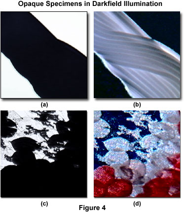
Darkfield illumination can often be a useful technique to image specimens that are seemingly opaque and difficult to observe under brightfield conditions. Presented in Figure 4 are two specimens that appear very dark in brightfield illumination, revealing no significant internal detail. Figure 4(a) is a brightfield image of Lycra spandex fibers, and Figure 4(b) is the same viewfield under darkfield illumination. The darkfield image readily displays the interwoven texture of fiber bundles characteristic of this synthetic polymer material. Another example is the small Apollo butterfly (Parnassius phoebus), which has very thick, opaque teardrop-shaped wing scales that appear dark and lacking in detail when imaged in brightfield illumination (Figure 4(c)). When wing scales from this butterfly are illuminated at a highly oblique angle, they appear bright with a considerable amount of detail and color superimposed on a black background.
In a darkfield microscope, when the rear of the objective is observed through a Bertrand lens or phase telescope, it appears to be filled with light. This faint diffracted light is reconstituted into the visible image at the plane of the eyepiece diaphragm (or the surface of a CCD or CMOS image sensor) with its contrast reversed to produce a bright image on a black background. Because darkfield microscopy eliminates the bright, undeviated light, this form of illumination is very wasteful of light and thus demands a high intensity illumination source. Microscope slides must be of the appropriate thickness, approximately one millimeter (plus or minus a tenth of a millimeter). Specimen slides and all optical surfaces in the light path must be scrupulously clean because every dirt speck will be mercilessly bright.
In general, specimens imaged under proper conditions of darkfield illumination are quite spectacular to observe (for example, try a drop of fresh blood in darkfield). Often specimens containing very low inherent contrast in brightfield microscopy shine brilliantly in darkfield. Such illumination is best for revealing outlines, edges, boundaries, and refractive index gradients. Unfortunately, darkfield illumination is less useful in revealing internal details.
Other types of specimens, including many that are stained, also respond well to illumination under darkfield conditions. Figure 5 illustrates darkfield digital images captured with the MIC-D microscope of three specimens, all of which produce good contrast in both brightfield and darkfield illumination. Presented in Figure 5(a) is a young starfish specimen that has been stained with hematoxylin and prepared as a whole mount. Darkfield illumination of this specimen produces excellent digital images that are rich in detail and contrast. In fact, many of the internal features of the starfish that are readily observed under darkfield illumination are obscured when the same specimen is viewed in brightfield.
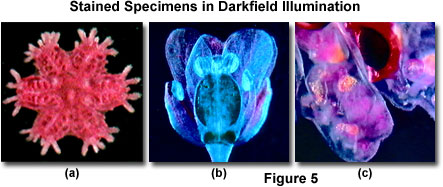
Another example of stained specimen observation in darkfield illumination is presented in Figure 5(b) for a multiply stained shepherd's purse (Capsella) embryo, which is an annual herb from the mustard family. The plant tissue is readily imaged in brightfield illumination, but also produces remarkable digital images with the MIC-D microscope operating under darkfield conditions. Finally, the marine bryozoan Pectinatella (Figure 5(c)) exhibits spectacular color and reveals fine specimen detail when viewed under both brightfield and darkfield illumination. In addition to the examples presented in Figure 5, a number of other specimens can also be viewed and photographed under a combination of both brightfield and darkfield illumination to achieve the desired effects.
During the first half of the twentieth century, darkfield microscopy had a very strong following and much effort was expended in optimizing darkfield condensers and illuminators. This intense interest slowly began to fade with the emergence of more advanced contrasting-enhancing techniques such as phase contrast, differential interference contrast (DIC), and Hoffman modulation contrast. Recently, a renewed interest in transmitted darkfield microscopy has arisen due to its advantages when used in combination with fluorescence microscopy.
Darkfield microscopy is still an excellent tool for both biological and medical investigations. It can be effectively used at high magnifications to photograph living bacteria, or at low magnifications to view and photograph cells, tissues, and whole mounts. Marine biologists continue to use darkfield illumination at low powers to observe and record data about fresh and salt-water organisms such as algae and plankton.
Contributing Authors
Thomas J. Fellers and Michael W. Davidson - National High Magnetic Field Laboratory, 1800 East Paul Dirac Dr., The Florida State University, Tallahassee, Florida, 32310.
BACK TO MIC-D MICROSCOPE ANATOMY
BACK TO THE OLYMPUS MIC-D DIGITAL MICROSCOPE
Questions or comments? Send us an email.
© 1995-2025 by Michael W. Davidson and The Florida State University. All Rights Reserved. No images, graphics, software, scripts, or applets may be reproduced or used in any manner without permission from the copyright holders. Use of this website means you agree to all of the Legal Terms and Conditions set forth by the owners.
This website is maintained by our
Graphics & Web Programming Team
in collaboration with Optical Microscopy at the
National High Magnetic Field Laboratory.
Last Modification Tuesday, Sep 11, 2018 at 03:59 PM
Access Count Since September 17, 2002: 19542
Visit the website of our partner in introductory microscopy education:
|
|