Interactive Java Tutorials
Electromagnetic Radiation
Electromagnetic radiation, the larger family of wave-like phenomena to which visible light belongs (also known as radiant energy), is the primary vehicle transporting energy through the vast reaches of the universe. This interactive tutorial explores the classical representation of an electromagnetic wave as a sine function, and enables the visitor to vary amplitude and wavelength to demonstrate how this function appears in three dimensions.
The tutorial initializes with a sine function simulating electromagnetic wave propagation traversing from left to right across the window. The oscillating electric field vectors of the virtual electromagnetic wave are represented by blue lines, while the magnetic field vectors are depicted in red. In order to operate the tutorial, use the mouse cursor to drag the wave back and forth in the window to observe how it appears from different angles. The Filled slider can be employed to vary the density of vector lines appearing within the sine function, and the Amplitude slider increases or decreases vector amplitude. Placing a checkmark in the Show Wave Color check box changes to the wave simulate the color matching the current Wavelength slider value. This slider can be utilized to alter the wavelength of the virtual wave between a range of 300 nanometers (ultraviolet) to 800 nanometers (infrared). As the Wavelength slider is translated, the color corresponding to the current wavelength is acquired by the virtual electromagnetic wave (provided the Show Wave Color check box is active), and the name (red, yellow, green, etc.) also appears above the slider bar.
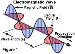
An electromagnetic wave travels or propagates in a direction that is oriented at right angles to the vibrations of both the electric (E) and magnetic (B) oscillating field vectors, transporting energy from the radiation source to an undetermined final destination. The two oscillating energy fields are mutually perpendicular (illustrated in Figure 1) and vibrate in phase following the mathematical form of a sine wave. Electric and magnetic field vectors are not only perpendicular to each other, but are also perpendicular to the direction of wave propagation. By convention, and to simplify illustrations, the vectors representing the electric and magnetic oscillating fields of electromagnetic waves are often omitted, although they are understood to still exist.

Whether taking the form of a signal transmitted to a radio from the broadcast station, heat radiating from a fireplace, the dentist's X-rays producing images of teeth, or the visible and ultraviolet light emanating from the sun, the various categories of electromagnetic radiation all share identical and fundamental wave-like properties. Every category of electromagnetic radiation, including visible light, oscillates in a periodic fashion with peaks and valleys (or troughs), and displays a characteristic amplitude, wavelength, and frequency that together define the direction, energy, and intensity of the radiation.
The classical schematic diagram of an electromagnetic wave presented in Figure 1 illustrates the sinusoidal nature of oscillating electric and magnetic component vectors as they propagate through space. As a matter of convenience, most illustrations depicting electromagnetic radiation purposely omit the magnetic component, instead representing only the electric field vector as a sine wave in a two-dimensional graphical plot having defined x and y coordinates. By convention, the y component of the sine wave indicates the amplitude of the electric (or magnetic field), while the x component represents time, the distance traveled, or the phase relationship with another sine wave.
A standard measure of all electromagnetic radiation is the magnitude of the wavelength (in a vacuum), which is usually stated in units of nanometers (one-thousandth of a micrometer) for the visible light portion of the spectrum. The wavelength is defined as the distance between two successive peaks (or valleys) of the waveform (see Figure 1). The corresponding frequency of the radiated wave, which is the number of sinusoidal cycles (oscillations or complete wavelengths) that pass a given point per second, is proportional to the reciprocal of the wavelength. Thus, longer wavelengths correspond to lower frequency radiation and shorter wavelengths correspond to higher frequency radiation. Frequency is usually expressed in quantities of hertz (Hz) or cycles per second (cps).
Contributing Authors
Mortimer Abramowitz - Olympus America, Inc., Two Corporate Center Drive., Melville, New York, 11747.
Matthew J. Parry-Hill and Michael W. Davidson - National High Magnetic Field Laboratory, 1800 East Paul Dirac Dr., The Florida State University, Tallahassee, Florida, 32310.
BACK TO ELECTROMAGNETIC RADIATION
