
Interactive Java Tutorials
Diffraction of Light
Several of the classical and most fundamental experiments that help explain diffraction of light were first conducted between the late seventeenth and early nineteenth centuries by Italian scientist Francesco Grimaldi, French scientist Augustin Fresnel, English physicist Thomas Young, and several other investigators. These experiments involve propagation of light waves though a very small slit (aperture), and demonstrate that when light passes through the slit, the physical size of the slit determines how the slit interacts with the light. This interactive tutorial explores the diffraction of a monochromatic light beam through a slit of variable aperture.
The tutorial initializes with a beam of monochromatic red (having a wavelength of 662 nanometers) light incident on a slit aperture (Aperture) that is 485 nanometers wide. Because the slit diameter is less than the wavelength of the incident light, wavefronts are diffracted as they pass through the slit. The diffraction pattern of the scattered waves is visible on a dark film screen behind the aperture, and is plotted as an intensity distribution beneath the screen. The diffraction minima are also calculated and constantly updated as the tutorial parameters are changed. To operate the tutorial, use the Wavelength slider to adjust the wavelength range of incident light between 400 and 700 nanometers. The Aperture slider can be employed to change the slit aperture size from 210 to 693 nanometers. Note that the sliders are integrated so that reducing the wavelength will also automatically reduce the aperture size to ensure that diffraction still occurs.
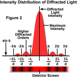
If the wavelength of light is much smaller than the aperture or slit width, a light wave simply travels onward in a straight line after passing through, as it would if no aperture were present (as presented in Figure 1). However, when the wavelength exceeds the size of the slit, diffraction of the light occurs, causing the formation of a diffraction pattern consisting of a bright central portion (the primary maximum), bounded on either side by a series of secondary maxima separated by dark regions (minima; see Figure 2). The maxima and minima are created by interference of diffracted light waves. Each successive bright band becomes less intense proceeding outward, away from the central maximum. The width of the central bright portion, and the spacing of the accompanying sidebands, depends on the size of the aperture (slit) and the wavelength of the light. This relationship can be described mathematically and demonstrates that the width of the central maximum decreases with decreasing wavelength and increasing aperture width, but can never be reduced to the size of a point light source.
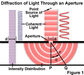
The intensity distribution of light diffracted by the single slit experiment is presented in Figures 1 and 2. It is assumed that both light beams in Figure 1 are composed of coherent, monochromatic waves emitted from a point source that is far enough away from the slit for the wavefronts to be considered linear and parallel. Light passing through aperture d on the right-hand side of the figure has a wavelength larger than the aperture and is diffracted, with the primary incident light beam landing at point P and the first secondary maximum occurring at point Q. As shown on the left-hand side of Figure 1, when the wavelength is much smaller than the aperture width (d), the wave simply travels through in a straight line, just as it would if it were a particle or no aperture were present. However, when the wavelength exceeds the size of the aperture, it is diffracted to produce a central peak containing most of the light intensity accompanied by secondary higher-order maxima and intensity minima governed according to the equation:
where q is the angle between the central incident propagation direction and the first minimum of the diffraction pattern, and m indicates the sequential number of the higher-order maxima. The light intensity is maximum at q = zero degrees, and decreases to a minimum (where the intensity is zero) at angles dictated by the equation above. The experiment produces a bright central maximum, which is bounded on both sides by secondary maxima, with the intensity of each succeeding secondary maximum decreasing as the distance from the center increases. Figure 2 illustrates this point with a plot of beam intensity versus diffraction radius. Note that the minima occurring between secondary maxima are positioned in multiples of p.
Both the experiment described above, and the classical demonstration of diffraction using light passing between the fingers, utilize a narrow slit as an aperture to produce a diffraction pattern. All optical instruments, including microscopes, utilize circular lenses and apertures, as does the human eye itself. Circular apertures produce similar diffraction phenomena, although with circular symmetry (instead of linear geometry, as in the case of slits). Therefore the diffraction pattern of a point source of light, if highly magnified, is seen to consist of a central bright disk surrounded by a concentric series of diffraction rings (the secondary maxima and minima). When a lens, such as a microscope objective lens, is properly focused, the light intensity at the minima between the bright rings in the pattern is zero. No matter how perfect the lens is, the secondary diffraction maxima cannot be eliminated nor can the central spot be reduced to a single point of light (unless the lens could be made with an infinite diameter).
Contributing Authors
Matthew J. Parry-Hill, Thomas J. Fellers, and Michael W. Davidson - National High Magnetic Field Laboratory, 1800 East Paul Dirac Dr., The Florida State University, Tallahassee, Florida, 32310.