
Refraction of Light
Refraction, or bending of light, occurs as light passes from one medium into another medium with a different refractive index. Refraction is an important characteristic of lenses, allowing them to focus a beam of light onto a single point, and is also responsible for a variety of familiar phenomena, such as the apparent distortion of objects partially submerged in water.
Refractive index is defined as the relative speed at which light moves through a material with respect to its speed in a vacuum. By convention, the refractive index of a vacuum is defined as having a value of 1.0. The index of refraction, n, of other transparent materials is defined through the equation:
where c is the speed of light, and v is the velocity of light in that material. Since the refractive index of a vacuum is defined as 1.0 and a vacuum is devoid of any material, the refractive indices of all transparent materials are therefore greater than 1.0. For most practical purposes, the refractive index of light through air (1.0003) can be used to calculate refractive indices of unknown materials. Refractive indices of some common materials are presented in Table 1 below.
|
||||||||||||||||||||||
Table 1
It is important to note that the speed at which refracted light travels is dependent upon the density of the materials it is traveling through. For instance, when light passes from a less dense medium, such as air, to a more dense medium, such as water, the speed at which the electromagnetic wave is traveling decreases. Alternatively, when light passes from a more dense medium to a less dense medium, the speed of the wave increases.
The angle at which refracted light travels, however, is dependent upon both the angle of incidence and the composition of the material into which it is entering. The normal can be defined as a line perpendicular to the boundary between two substances. Light passes into the boundary at an angle to the normal and is refracted according to Snell's Law:
where n represents the refractive indices of material 1 and material 2 and q symbolizes the angles of light traveling through these materials with respect to the normal. There are several important points that can be drawn from this equation. When n(1) is greater than n(2), the angle of refraction is always smaller than the angle of incidence. Alternatively, when n(2) is greater than n(1) the angle of refraction is always greater than the angle of incidence. When the two refractive indices are equal (n(1) = n(2)), then the light is passed through without refraction.
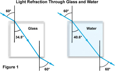
The concept of refractive index is illustrated in Figure 1 below, focusing on the case of light passing from air through both glass and water. Notice that while both beams enter the denser material through the same angle of incidence with respect to the normal (60 degrees), the refraction for glass is almost 6 degrees greater than that for water due to the higher refractive index of glass.
Scientists have found that the index of refraction varies with the frequency of radiation (or wavelength) of light. This phenomenon occurs in conjunction with all transparent media and has been termed dispersion. Therefore, when measuring the refractive index of a transparent substance, the particular wavelength used in the measurement must be identified. Below, Table 2 details the dispersion of three independent wavelengths in various media.
|
||||||||||||||||||||||||||
Table 2
The most commonly used wavelength to measure refractive index is that emitted by a sodium lamp, which has an average wavelength of 5.893 nanometers. This light is termed the D line spectrum, and represents the yellow light listed in Table 2 above. Likewise, F line and C line spectra correspond to blue and red light of specific wavelengths emitted by hydrogen. These spectra are fundamental in the calculation of dispersion, which can be quantitatively defined as:
where n is the refractive index of the material at a particular wavelength designated by D, F, and C, which represent the spectral lines of sodium and hydrogen as discussed above. The relationship is such that as the wavelength of light increases, the refractive index decreases. However, many factors play a role in the dispersion of various materials, including their elemental and molecular composition. Several inorganic solids, such as chromates, dichromates, cyanides, vanadates, and halide complexes, have unusually high dispersions. Yet, organic substituents may also contribute to high dispersion.
| Interactive Java Tutorial | |||||||||||
|
|||||||||||
Refraction of light is particularly important in the construction and physics of lenses. Remember, that when the beam of light exited both the glass and water in Figure 1, it was again refracted at the same angle at which it entered the material. This concept is essential in the functioning of lenses, though the shape of the lens significantly affects the resulting image. In a convex lens, as illustrated below in Figure 2, light waves reflected from the object, in this case a giraffe, are bent towards the optical center of the lens and converge on the focal point.
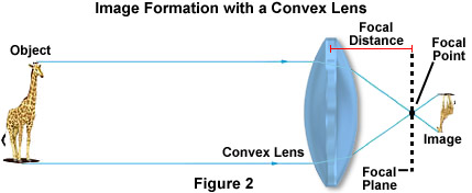
The relative position of the object with respect to the front focal point of the lens determines how the object is imaged. If the object is beyond twice the length of the focal point, then it appears smaller and inverted and must be imaged by an additional lens in order to magnify the size. However, when the image is closer to the lens than the focal point, the image appears upright and larger, as can be easily demonstrated with a simple magnifying glass.
| Interactive Java Tutorial | |||||||||||
|
|||||||||||
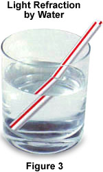
Due to the refraction of light, a common optical illusion occurs when objects are visualized in water. A simple drinking straw in a glass filled with water, as illustrated in Figure 3, is a prime example of this occurrence. In this example, waves of light must first pass through the water, then through the glass/water boundary, and finally through the air. The light waves reflected from the ends of the straw are refracted to a greater degree than those coming from the center of the straw, making the straw appear magnified and slightly distorted.
The same phenomenon can be used to determine the refractive index of a liquid with an optical microscope. To do so, a flat cell capable of holding liquid with a mark (or graduations) must be placed on the inside glass surface. Also, one of the microscope eyepieces must have a graduated reticle inserted at the primary image plane for line width measurements of the mark in the flat cell. Before adding the liquid of unknown refractive index to the cell, the microscope should be focused on the mark at the bottom of the cell and a measurement of the mark's position on the reticle noted. Next, a small amount of liquid should be added to the cell and the microscope refocused on the mark (through the liquid) and a new measurement taken. The microscope should then be finally focused on the surface of the liquid, and a third reading recorded by measuring the position of the mark on the reticle. The refractive index of the unknown liquid can then be calculated using the following equation:
where D(measured) is the measured depth (from the surface of the liquid to the position of the mark on the empty cell) using the microscope and D(apparent) is the mark measurement with and without liquid.
The critical angle of reflection is another key concept in the study of light refraction and is illustrated below in Figure 4. When light passes through a medium of high refractive index into a medium of lower refractive index, the incident angle of the light waves becomes an important factor. If the incident angle increases past a specific value (dependent upon the refractive index of the two media), it will reach a point where the angle is so large that no light is refracted into the medium of lower refractive index.
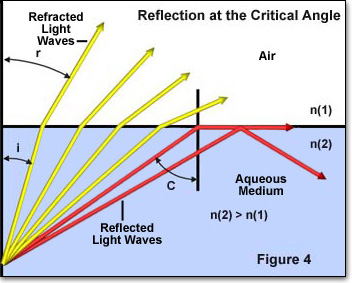
In Figure 4, individual light rays are represented by either red or yellow colored arrows moving from a medium of high refractive index (n(2)) to one of lower refractive index (n(1)). The angle of incidence of each individual light ray is denoted by i and the angle of refraction by r. The four yellow light rays all have an angle of incidence (i) low enough to pass through the interface between the two media. However, the two red light rays have incident angles that exceed the critical angle (approximately 41 degrees) and are reflected either into the boundary between the media or back into the high refractive index medium. This phenomenon takes place when the angle of refraction (angle r in Figure 4) becomes equal to 90 degrees and Snell's law reduces to:
where (q) is now termed the critical angle C. If the medium of lesser refractive index is air (n = 1.00), the equation further reduces to:
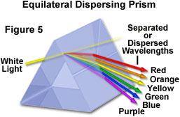
As discussed previously, another important feature of light refraction is that the wavelength of light has an impact on the amount of refraction that occurs within a medium. In fact, the amount of refraction that takes place is inversely proportional to the wavelength of the incident light. Thus, shorter wavelength visible light is refracted at a greater angle than longer wavelength light. Consequently, when white light, which is composed of all the colors in the visible spectrum, is passed through a glass prism, it is dispersed into its component colors in a manner that is dependent upon the individual wavelengths. Low frequency visible light (600 nanometers and greater) is refracted at a smaller angle than higher frequency light, which results in a rainbow-like effect, as illustrated below in Figure 5.
This same phenomenon is also responsible for chromatic aberration. When white light is passed through a simple convex lens, several focal points arise in close proximity that correspond to the minor refractive index differences of the component wavelengths. This effect tends to produce colored (either red or blue, depending upon focus) halos surrounding the images of objects. Correction of this aberration is usually accomplished through the use of combinations of two or more lens elements composed of materials having different dispersive properties, such as an achromatic lens constructed with both crown and flint glasses.
| Interactive Java Tutorial | |||||||||||
|
|||||||||||
Over the years, humans have made many devices that make use of the fact that light can be refracted, as well as reflected and focused. The most common example is a camera, which is designed to create sharp and focused images onto an emulsion of film or the surface of a charge-coupled device (CCD) to produce an accurate image. Other optical devices that exploit these characteristics of light include microscopes and telescopes, which enable the viewing of of objects that are invisible to the unaided human eye, regardless of whether they are located on the head of a pin or in a distant galaxy.
Contributing Authors
Mortimer Abramowitz - Olympus America, Inc., Two Corporate Center Drive., Melville, New York, 11747.
Shannon H. Neaves and Michael W. Davidson - National High Magnetic Field Laboratory, 1800 East Paul Dirac Dr., The Florida State University, Tallahassee, Florida, 32310.