Introduction to Lenses
The term lens is applied to a piece of glass or transparent plastic, usually circular in shape, that has two surfaces that are ground and polished in a specific manner designed to produce either a convergence or divergence of light. The two most common types of lenses are concave and convex lenses, which are illustrated below in Figure 1.
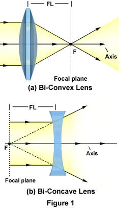
A common bi-convex lens is considered a positive lens because it causes light rays to converge, or concentrate, to form a real image. Real images can be projected onto a screen or viewed without the aid of additional lenses, but appear inverted or opposite the orientation of the object viewed. These lenses are thicker at the center than the periphery and appear to be bulging outward in a hemispherical manner with a constant curvature of radius. The bi-convex lens illustrated in Figure 1(a) has a focal point at point F with a corresponding focal length FL. Since this convex lens is symmetrical with equal curvature angles on both sides of the lens, there is another focal point of the same length as FL on the other side of the lens, although it is not illustrated.
Concave lenses, on the other hand, are considered to be negative lenses because light waves passing through them diverge, or are scattered away from, a focal point or centerline. This divergence occurs because the lens is thinner in the center and thicker on the periphery, causing light entering the lens to be refracted away from its center. The bi-concave lens illustrated in Figure 1(b) operates in a manner similar to concave mirrors, with which light waves are refracted as if they were emitted from a point behind the lens. These waves converge on a negative focal point, labeled F in Figure 2(b). Since light does not actually converge on this point, it is called a virtual focus point and the corresponding image is a virtual image. Virtual images appear erect or in the same orientation as the real object, but can only be viewed or projected with the aid of another lens.
| Interactive Java Tutorial | |||||||||||
|
|||||||||||
As illustrated in Figure 1, a lens operates by refracting incoming light waves at points where they enter and exit the lens. The angle of that refraction, however, and therefore the focal length of a lens, depends upon the material of which it is composed. Materials with a high index of refraction have a shorter focal length than those with lower refractive indices (RI). For example, lenses made of synthetic polymers such as Lucite (RI = 1.47) have a lower refractive index than glass (RI = 1.51), which results in their having a slightly longer focal length. Fortunately, the refractive indices of Lucite and glass are so close together that Lucite can be used in place of glass in many lens applications, such as the popular disposable camera. As another example, a lens made of pure diamond (RI = 2.42) would have a focal length significantly less than either glass or Lucite, though the cost of designing such a lens would be prohibitive.
Lenses of various shapes, sizes, and materials enjoy a wide variety of usage. For instance, single lenses able to form real images are found in tools used for simple magnification, such as magnifying glasses, eyeglasses, single-lens cameras, viewfinders, and contact lenses. More complex devices, such as compound microscopes, telescopes, and binoculars, use a combination of lenses in order to enhance magnification and other desirable optical properties. However, these instruments are commonly plagued by lens errors that distort images by a variety of mechanisms associated with aberrations, or defects, resulting from the spherical geometry of lens surfaces. There are several types of lens errors, but the general effect of optical aberrations in a microscope is the appearance of faults in the tiny features and details of an image that is being observed. Thus, aberration is one of many factors that should be considered when deciding what kind of lens to use.
Most lenses are classified according to their two principal surfaces and curvature patterns, since the type of refraction that occurs when light travels through a lens is dependent upon the geometry of that lens. Basic lens groups are typically divided into two sub-categories, the convergent lenses and the divergent lenses. Each category contains several different lens types, which are addressed individually below.
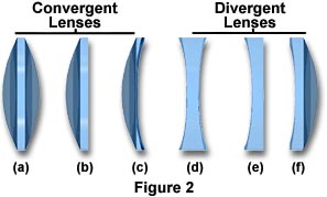
The Bi-Convex Lens - The simplest magnifying lens is the bi-convex (sometimes called the double-concave) convergent lens that condenses light rays into a focal point, as illustrated in Figure 1(a). The focal length of a bi-convex lens, also featured as Figure 2(a), is dependent upon the curvature angle of its faces. Higher angles of curvature result in shorter focal lengths due to the fact that light waves are refracted at a greater angle with respect to the centerline of the lens. The symmetric nature of bi-convex lenses minimizes spherical aberration in applications where the image and object are at symmetrical distances. These lenses are typically used for focusing and image magnification.
The Bi-Concave Lens - Concave lenses, like the one illustrated in Figure 2(d), are primarily used for diverging light and image reduction, as well as increasing system focal lengths and collimating converging light beams. The bi-concave (sometimes called the double-concave) lens refracts parallel input rays so that they diverge away from the optical axis on the output side of the lens, but form a negative focal point in front of the lens, as illustrated in Figure 1(b). While the output rays do not actually cross to form a focal point, they do appear to be diverging from a virtual image located on the object side of the lens. Bi-concave lenses are often coupled with other lenses in order to reduce the focal lengths of optical systems.
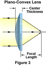
The Plano-Convex Lens - Figure 2(b) and Figure 3 depict typical plano-convex lenses that have one positive hemispherical side and one flat side. Plano-convex lenses are convergent, focusing parallel rays of light to a positive focal point, as illustrated in Figure 3. Thus, these lenses form real images, which can be projected or manipulated by spatial filters. The asymmetry of plano-convex lenses minimizes spherical aberration in applications where the object and image lie at unequal distances from the lens. When the curved surface of the lens is oriented toward the object, the sharpest possible focus is achieved. Plano-convex lenses are useful for collimating diverging beams of light and for applying focus to an optical system.

The Concavo-Convex Lens - The third type of convergent lens is the concavo-convex lens, which is depicted in Figure 2(c) and Figure 4. More commonly known as the positive (converging) meniscus lens, this lens also has an asymmetric structure. One of its faces is in a convex hemispherical shape, while the other is slightly concave. Meniscus lenses are used most often in conjunction with another lens to produce an optical system of a longer or shorter focal length than the original lens. For instance, a positive meniscus lens can be placed after a plano-convex lens to shorten its focal length without decreasing the performance of the optical system. Positive meniscus lenses have a greater curvature radius on the concave side of the lens than on the convex side, which enables the formation of a real image.
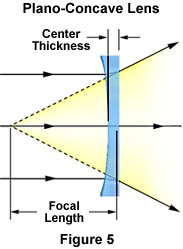
The Plano-Concave Lens - The plano-concave lens, illustrated in Figure 2(e) and Figure 5, is a divergent lens that has a negative focal point and produces a virtual image. When a collimated light beam is incident on the curved surface of a plano-concave lens, the exit side forms a divergent beam. This beam appears to emerge from a smaller virtual point source than if the plane surface had faced the collimated beam. Plano-concave lenses are used to expand light beams or to increase focal lengths in existing optical systems.
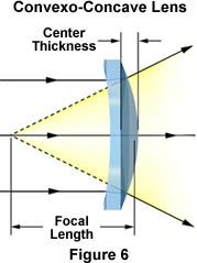
The Convexo-Concave Lens - This lens is commonly referred to as a negative (divergent) meniscus lens, since its concave surface has a lower curvature radius than its convex surface, as illustrated in Figure 2(f) and in Figure 6. This type of lens can be used to reduce or eliminate spherical aberration in optical systems with which the lens is coupled and can be combined with other lenses to produce increased resolution capabilities.
Contributing Authors
Mortimer Abramowitz - Olympus America, Inc., Two Corporate Center Drive., Melville, New York, 11747.
Shannon H. Neaves and Michael W. Davidson - National High Magnetic Field Laboratory, 1800 East Paul Dirac Dr., The Florida State University, Tallahassee, Florida, 32310.
