
Light Filtration
Most light sources emit a broad range of wavelengths that cover the entire visible light spectrum. For most simple lighting applications, such as interior lights, flashlights, and headlights, this wide wavelength spectrum is acceptable and quite useful. In many instances and for certain applications, however, it is desirable to produce light that has a restricted wavelength spectrum. This can be easily accomplished through the use of specialized filters that transmit some wavelengths of electromagnetic radiation while selectively absorbing or reflecting others.
Color filters are usually constructed using transparent pieces of dyed glass, plastic, or lacquered gelatin (e.g. Wratten filters) that have been treated to selectively transmit the desired wavelengths while restricting unwanted wavelengths. The two most common types of filters in use today are absorption filters that absorb unwanted wavelengths and interference filters that remove selected wavelengths by internal destructive interference and reflection. When using any filter, however, a small amount of the incident light is reflected from the surface of the filter regardless of its construction and another small portion of the light is absorbed. Nevertheless, the occurrence is usually very minimal and does not interfere with the primary function of the filter.
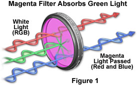
Absorption Filters - These filters are generally constructed of dyed glass, lacquered gelatin, or synthetic polymers (plastics) and have a wide range of applications. They are frequently used to create special effects in a number of photography applications and are widely employed in the cinema industry. In addition, absorption filters are commonly found in signs and traffic signals, as well as directional signals on vehicles such as automobiles, boats, and airplanes.
A typical absorption filter is illustrated above in Figure 1. In this example, a magenta filter that is designed to adapt to a camera lens is met by three incident light waves. Though they are illustrated as red, green, and blue waves, they are intended to represent all of the colors that comprise white light. Notice the filter selectively transmits the red and blue portions of the incident white light spectrum, but absorbs most of the green wavelengths. Remember, as discussed in the primary colors article, the color magenta is obtained by subtracting green from white light.
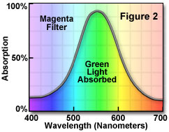
In Figure 2, the light-modulating properties of another typical color filter are illustrated. In this case, a color correction filter that adds a factor of 50 color compensating (cc) units to incident light, a concept that will be discussed in more detail below, is being examined. The percentage of filter absorption is plotted against the visible wavelengths that are passed through the filter. The peak intensity of absorbed light falls at about 550 nanometers, right in the center of the green region of visible wavelengths. However, the plot also shows that some light in the blue and red regions is absorbed, indicating that this filter is not perfect and that a small portion of all wavelengths are hindered by it. Common to most filters, this type of unwanted absorption is often termed secondary absorption. If this filter were perfect, the plot in Figure 2 would have a very sharp peak centered in the green region that trailed off to zero absorption at non-green wavelengths. Yet, this is a nearly impossible feat to accomplish in the real world where visible absorption filters need to be manufactured at reasonable prices.
| Interactive Java Tutorial | |||||||||||
|
|||||||||||
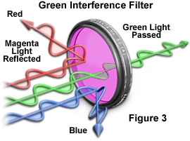
Interference Filters - These filters differ from absorption filters in the fact that they reflect and destructively interfere with unwanted wavelengths of light instead of absorbing them. They are often termed dichroic because they appear one color on the side from which light is reflected and another on the side in which transmitted light shines through. For example, in the magenta dichroic filter illustrated below in Figure 3, green light is reflected from the face of the filter and magenta light is transmitted from the back of the filter.
Dichroic filters are far more accurate and efficient in their ability to block unwanted wavelengths than gel and glass absorption filters. Manufactured from multi-layered thin film coatings that are deposited onto optical-grade glass using vacuum deposition, these filters have four basic design types: short wavelength pass, long wavelength pass, bandpass and notch filters. Short and long wavelength pass dichroic filters act as the names imply, only allowing transmission of narrow bands of short or long wavelengths and reflecting the unwanted wavelengths. Bandpass dichroic filters, however, are the most common and are designed to transmit selected wavelengths in the visible region. Figure 4 illustrates the transmission spectrum of a typical bandpass dichroic filter.
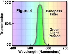
In this example, the wavelengths that are transmitted by the filter are plotted against the percentage of transmission. Note that the wavelength maximum is at 550 nanometers, directly in the center of the green region. Moreover, the graph also shows virtually no passage of unwanted wavelengths and secondary transmission is almost nonexistent, a testament to the effectiveness of this type of filter.
The final type of dichroic filters are known as notch wavelength filters, which operate by "notching out" or eliminating unwanted wavelengths. Notch filters are essentially the opposite of bandpass dichroic filters. For instance, instead of selectively transmitting the desired green wavelengths, like the bandpass filter plotted in Figure 4, a notch filter would eliminate the unwanted red and blue color wavelengths via reflection. Thus, the same result is effectively achieved by both filters, but in a contrary manner.
Dichroic filters are commonly used for a number of applications, including specialized filtration for optical microscopy and photography. Generally, high-quality color photography enlargers employ dichroic filters rather than absorption filters to finely tune the color of light that is passed through color negatives and transparencies. This allows the photographer a particularly high degree of color correction control over photographic prints.
Color Correction - In order to ensure accurate color rendition, photography enlargers and microscopists often must make slight corrections in the color of illumination. This is usually accomplished with Kodak Color Compensation (CC) filters that can easily be placed in the light path of the enlarger or microscope. A wide variety of other manufacturers also produce these filters, however, which are fabricated with dyed gels or dichroic glass. Color Compensation filters are labeled with a number that corresponds to the filter's light-absorbing ability, typically in the somewhat arbitrary range of 05, 10, 20, 30, 40, and 50, as shown in the cyan filter table illustrated below.
|
|||||||||||||||||||||||||||||||||||||||||||||||||||||
Table 1
In Table 1, a cyan filter range from 05 to 50 is featured and the background color of each row of the table corresponds to the approximate filter color featured in that section. As the label numbers increase, the filters become increasingly darker, which results in a greater amount of light being absorbed. Notice that the 30 cyan filter (referred to as a CC30C (cyan) filter) reduces the intensity of the complementary color by 50%, which is commonly referred to as one exposure step, or f-stop.
Color Compensation filters are available as Wratten filters ranging in size from 2" x 2" or 3" x 3," and in 6 different colors: blue, yellow, green, magenta, cyan and red. They are also available in a wide variety of densities. Since there are so many factors involved, the easiest way to remember which type of filter should be used to achieve a desired effect is to consult a color compensating triangle like the one illustrated in Figure 5 or a chart, such as the one shown in Table 2.
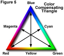
In order to use the color compensating triangle, the arrows from vertex to opposite side or from side to opposite vertex should be followed. For instance, an arrow connects green and magenta on the triangle. This means that a green cast can be removed through the use of a Color Compensation magenta filter, and vice versa. Table 2 may also be referred to for the correct Color Compensation filter color. However, to determine the appropriate density of the chosen Color Compensation filter, test exposures must be made.
|
|||||||||||||||||||||||
Table 2
When conducting experiments involving photomicrography, color compensating filters are often placed into the light path of an instrument. This is most easily accomplished by cutting the filter into a circle and inserting it into the light path just behind the diffusion filter. An alternative method is to purchase small metal frames that hold Wratten filters from Kodak, which can then be placed on the light port of the microscope just above the field diaphragm. This technique allows for a global color correction in the resulting photomicrographs.
Contributing Authors
Mortimer Abramowitz - Olympus America, Inc., Two Corporate Center Drive., Melville, New York, 11747.
Shannon H. Neaves and Michael W. Davidson - National High Magnetic Field Laboratory, 1800 East Paul Dirac Dr., The Florida State University, Tallahassee, Florida, 32310.