
QX3 Microscope Body Disassembly
The Intel Play QX3 Computer Microscope body is the most important component of this toy microscope. The body can be removed from the stand and used in a hand-held standalone mode to image specimens that are removed from the computer and microscope stand (up to eight feet away).
There is no reason for users to disassemble the microscope body, except to more closely examine the individual components or to modify and upgrade objective lenses. Another reason might be to place a contrast enhancing device at the rear focal plane of the objectives, but modifications such as this require a considerable degree of skill and expert knowledge of microscopy. Repair of dysfunctional interior components, such as an objective or the digital imaging electronics, is best left to experts in the Mattel support group.
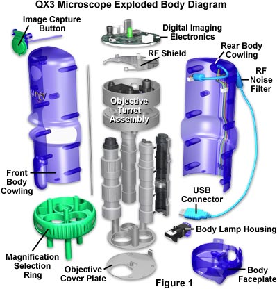
That said, we will now describe a detailed procedure for disassembly of the microscope body and discuss various aspects of the internal components. Before disassembly, first remove the body from the microscope stand and unplug the USB cable from the rear of the host computer. Next, follow the step-by-step procedure outlined below while referring to the exploded body diagram illustrated in Figure 1. The only tools needed to completely disassemble the body are a Phillips-head screwdriver, a razor knife, a jeweler's flat-blade screwdriver, and a pair of needle nosed pliers.
For the purposes of this discussion, we will define the Front of the microscope body as that part containing the image capture button and magnification selection ring when facing the observer. The Rear of the microscope body will contain the USB cable, the body lamphouse and its attachment screw, and a set of depressions containing Phillips-head screws that hold the two body cowlings together.
- Hold the body in one hand with the rear of the microscope body facing you and locate the single Phillips-head screw that fastens the body lamp housing into the body. Use a screwdriver to loosen the screw and remove the lamp housing. The screw is retained in the lamp housing by a nylon lock washer to ensure it does not become lost during lamp replacement. Note the electrical contacts (Figure 2) that connect the lamp housing to the microscope body circuitry. Set the lamp housing aside until the body is reassembled.
- Locate the eight depressions that contain Phillips-head screws, which secure the front and rear body cowlings together. Use a screwdriver to remove all eight self-tapping machine-head screws. They are not provided with nylon lock washers and can be completely removed from the rear body cowling. Place them in a small container for protection against loss.
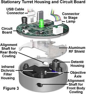
- The front and rear body cowlings and the body faceplate are now free to be removed from the interior objective turret/digital imaging electronics assembly (hereinafter referred to as the turret/electronics assembly). This assembly contains four angled alignment shafts in the upper turret housing (Figure 3), which also contains the objective positioning détente (a stainless steel ball bearing) and the dichroic infrared filter window, along with the RF (radio frequency) shield for the digital imaging electronics. At the other end of the body, the faceplate also has four similar alignment shafts. Together these eight angled shafts provide correct alignment and positioning for the two body cowlings with respect to the turret and body faceplate.
- Holding the rear body cowling and USB cable with one hand, slowly wiggle the front body cowling free from the body faceplate, the turret/electronics assembly, and the rear cowling of the microscope body. This involves loosening a set of four cylindrical tabs in the front body cowling from two alignment shafts in the body faceplate and two alignment shafts in the upper turret housing. When the cylindrical tabs have cleared the angled alignment shafts, the front body cowling can be removed from the microscope.
- After removing the front body cowling, wiggle the body faceplate until it breaks loose from the two cylindrical tabs in the lower rear body cowling. Remove the faceplate and set it aside. What will remain is the objective turret/electronics assembly with its connecting wires attached to the USB port cable in the rear body cowling of the microscope.
- To remove the turret/electronics assembly, two electrical connectors must be first be removed (Figure 3) from the digital electronics circuit board (labeled USB Power Source and Substage Lamp Power Source in Figure 4). One connector contains five wires (colored red, yellow, blue, green, and purple) that travel through a molded blue plastic conduit to the body electrical contact pads that supply current to the microscope stand. This connector is easy to remove and can simply be pulled from the circuit board. The other connector is more difficult, because it is held into the circuit board recepticle with the assistance of a yellow polymeric glue-like substance. The second connector also contains five wires (two colored black, and the other three red, green, and white) that compose the USB cable and are attached to a magnetic noise filter inside the microscope body. Use a razor knife to remove as much of the polymer as possible, then gently wiggle the connector free and pull it away from the circuit board. This action will be obvious to Mattel support engineers and will violate the manufacturer's warranty. After both connectors are removed, the rear body cowling containing the USB cable can be removed.
- The body faceplate can now be removed from the objective turret/electronics assembly and placed aside until body reassembly time.
- The digital electronics circuit board is attached to the stationary turret housing with three Phillips-head screws that have a flat washer extending from the screw head (a one-piece unit). During assembly at the factory, the position of these screws is marked with a red polymeric dye that overflows onto the surface of the circuit board. Removing and replacing the screws will be another clue to Mattel support engineers that the body has been disassembled.
- After the screws have been removed from the circuit board, it can be gently pulled free from the stationary turret housing to expose a small plastic box containing the dichroic window and the objective positioning détente housing (Figure 3). The underside of the circuit board is protected by an aluminum RF (radio frequency) shield that is soldered onto the board. There is also drilled boss inside the stationary turret housing that is covered with the yellow polymeric glue-like substance. Removal of the polymer reveals a snap ring securing a spring-loaded stainless steel rod that serves as the central axle to support free rotation of the objective turret.
- Using the razor knife, remove all of the polymer resin from the tip of the axle and snap ring. Then place the objective turret assembly securely on a desktop and press down, forcing the axle and snap ring to rise above the cylindrical axle boss in the stationary turret housing. Use a jeweler's screwdriver or needle nosed pliers to remove the snap ring, freeing the stationary turret housing from the axle and the rest of the turret assembly. Set the stationary turret housing aside until reassembly. Add the snap ring to the container holding small parts for the microscope.
- The objective turret assembly is held together by three Phillips-head screws that reside deep within recessed cavities in the upper objective turret housing that secures the rear barrel of each objective to the green magnification selection ring. There are three similar screws at the other end of the objective turret that fasten the objective face plate to the magnification selection ring.
- Remove the three Phillips-head screws in the upper turret housing (nearer the rear of the objectives), and pull the housing free from the magnification ring. The axle and spring assembly will be removed with the housing, as will the 10x objective, which is screwed into the housing with a set of threads molded onto the objective barrel. Be very careful not to screw the 10x objective into or out of the housing to avoid disturbing factory preset parfocal settings of the microscope.
- After the upper housing, axle, and 10x objective assembly have been removed from the turret, the 60x and 200x objectives can be also be removed by sliding them toward the rear of the housing.
- At this point, all that is left is the green magnification ring and the objective face plate, which are attached to each other by three Phillips-head screws that reside deep within three cylindrical bosses that double as spacers between the magnification ring and the face plate. No further disassembly of the microscopy body is required.


The QX3 microscope body can be reassembled by reversing the order of the disassembly instructions. Be careful to replace the objectives in the correct order within the magnification ring, adjacent to the white magnification indicator on the outside of the knurled ring. This is not difficult to accomplish, because each objective has a different diameter and they are correctly positioned within the magnification ring by a tab on the barrel.
BACK TO INTEL PLAY QX3 MICROSCOPE ANATOMY
Questions or comments? Send us an email.
© 1995-2025 by Michael W. Davidson and The Florida State University. All Rights Reserved. No images, graphics, software, scripts, or applets may be reproduced or used in any manner without permission from the copyright holders. Use of this website means you agree to all of the Legal Terms and Conditions set forth by the owners.
This website is maintained by our
Graphics & Web Programming Team
in collaboration with Optical Microscopy at the
National High Magnetic Field Laboratory.
The QX3 microscope design is copyrighted © 2025 by Mattel, Inc. Intel® Play™ is a registered trademark of the Intel Corporation. These companies reserve all of their rights and privileges under copyright law. The material contained in this website is solely the opinion of the authors and is intended for eduational use only.
Last Modification Friday, Nov 13, 2015 at 02:18 PM
Access Count Since December 24, 1999: 41756
Visit the official Intel Play website:
![]()