
Reflection of Light
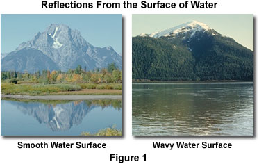
Reflection of light (and other forms of electromagnetic radiation) occurs when the waves encounter a surface or other boundary that does not absorb the energy of the radiation and bounces the waves away from the surface. The simplest example of visible light reflection is the surface of a smooth pool of water, where incident light is reflected in an orderly manner to produce a clear image of the scenery surrounding the pool. Throw a rock into the pool (see Figure 1), and the water is perturbed to form waves, which disrupt the reflection by scattering the reflected light rays in all directions.
Some of the earliest accounts of light reflection originate from the ancient Greek mathematician Euclid, who conducted a series of experiments around 300 BC, and appears to have had a good understanding of how light is reflected. However, it wasn't until a millennium and a half later that the Arab scientist Alhazen proposed a law describing exactly what happens to a light ray when it strikes a smooth surface and then bounces off into space.
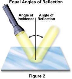
The incoming light wave is referred to as an incident wave, and the wave that is bounced away from the surface is termed the reflected wave. Visible white light that is directed onto the surface of a mirror at an angle (incident) is reflected back into space by the mirror surface at another angle (reflected) that is equal to the incident angle, as presented for the action of a beam of light from a flashlight on a smooth, flat mirror in Figure 2. Thus, the angle of incidence is equal to the angle of reflection for visible light as well as for all other wavelengths of the electromagnetic radiation spectrum. This concept is often termed the Law of Reflection. It is important to note that the light is not separated into its component colors because it is not being "bent" or refracted, and all wavelengths are being reflected at equal angles. The best surfaces for reflecting light are very smooth, such as a glass mirror or polished metal, although almost all surfaces will reflect light to some degree.
| Interactive Java Tutorial | |||||||||||
|
|||||||||||
Because light behaves in some ways as a wave and in other ways as if it were composed of particles, several independent theories of light reflection have emerged. According to wave-based theories, the light waves spread out from the source in all directions, and upon striking a mirror, are reflected at an angle determined by the angle at which the light arrives. The reflection process inverts each wave back-to-front, which is why a reverse image is observed. The shape of light waves depends upon the size of the light source and how far the waves have traveled to reach the mirror. Wavefronts that originate from a source near the mirror will be highly curved, while those emitted by distant light sources will be almost linear, a factor that will affect the angle of reflection.
According to particle theory, which differs in some important details from the wave concept, light arrives at the mirror in the form of a stream of tiny particles, termed photons, which bounce away from the surface upon impact. Because the particles are so small, they travel very close together (virtually side by side) and bounce from different points, so their order is reversed by the reflection process, producing a mirror image. Regardless of whether light is acting as particles or waves, however, the result of reflection is the same. The reflected light produces a mirror image.
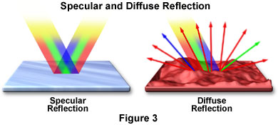
The amount of light reflected by an object, and how it is reflected, is highly dependent upon the degree of smoothness or texture of the surface. When surface imperfections are smaller than the wavelength of the incident light (as in the case of a mirror), virtually all of the light is reflected equally. However, in the real world most objects have convoluted surfaces that exhibit a diffuse reflection, with the incident light being reflected in all directions. Many of the objects that we casually view every day (people, cars, houses, animals, trees, etc.) do not themselves emit visible light but reflect incident natural sunlight and artificial light. For instance, an apple appears a shiny red color because it has a relatively smooth surface that reflects red light and absorbs other non-red (such as green, blue, and yellow) wavelengths of light. The reflection of light can be roughly categorized into two types of reflection. Specular reflection is defined as light reflected from a smooth surface at a definite angle, whereas diffuse reflection is produced by rough surfaces that tend to reflect light in all directions (as illustrated in Figure 3). There are far more occurrences of diffuse reflection than specular reflection in our everyday environment.
| Interactive Java Tutorial | |||||||||||
|
|||||||||||
To visualize the differences between specular and diffuse reflection, consider two very different surfaces: a smooth mirror and a rough reddish surface. The mirror reflects all of the components of white light (such as red, green, and blue wavelengths) almost equally and the reflected specular light follows a trajectory having the same angle from the normal as the incident light. The rough reddish surface, however, does not reflect all wavelengths because it absorbs most of the blue and green components, and reflects the red light. Also, the diffuse light that is reflected from the rough surface is scattered in all directions.
Perhaps the best example of specular reflection, which we encounter on a daily basis, is the mirror image produced by a household mirror that people might use many times a day to view their appearance. The mirror's smooth reflective glass surface renders a virtual image of the observer from the light that is reflected directly back into the eyes. This image is referred to as "virtual" because it does not actually exist (no light is produced) and appears to be behind the plane of the mirror due to an assumption that the brain naturally makes. The way in which this occurs is easiest to visualize when looking at the reflection of an object placed on one side of the observer, so that the light from the object strikes the mirror at an angle and is reflected at an equal angle to the viewer's eyes. As the eyes receive the reflected rays, the brain assumes that the light rays have reached the eyes in a direct straight path. Tracing the rays backward toward the mirror, the brain perceives an image that is positioned behind the mirror. An interesting feature of this reflection artifact is that the image of an object being observed appears to be the same distance behind the plane of the mirror as the actual object is in front of the mirror.
The type of reflection that is seen in a mirror depends upon the mirror's shape and, in some cases, how far away from the mirror the object being reflected is positioned. Mirrors are not always flat and can be produced in a variety of configurations that provide interesting and useful reflection characteristics. Concave mirrors, commonly found in the largest optical telescopes, are used to collect the faint light emitted from very distant stars. The curved surface concentrates parallel rays from a great distance into a single point for enhanced intensity. This mirror design is also commonly found in shaving or cosmetic mirrors where the reflected light produces a magnified image of the face. The inside of a shiny spoon is a common example of a concave mirror surface, and can be used to demonstrate some properties of this mirror type. If the inside of the spoon is held close to the eye, a magnified upright view of the eye will be seen (in this case the eye is closer than the focal point of the mirror). If the spoon is moved farther away, a demagnified upside-down view of the whole face will be seen. Here the image is inverted because it is formed after the reflected rays have crossed the focal point of the mirror surface.
Another common mirror having a curved-surface, the convex mirror, is often used in automobile rear-view reflector applications where the outward mirror curvature produces a smaller, more panoramic view of events occurring behind the vehicle. When parallel rays strike the surface of a convex mirror, the light waves are reflected outward so that they diverge. When the brain retraces the rays, they appear to come from behind the mirror where they would converge, producing a smaller upright image (the image is upright since the virtual image is formed before the rays have crossed the focal point). Convex mirrors are also used as wide-angle mirrors in hallways and businesses for security and safety. The most amusing applications for curved mirrors are the novelty mirrors found at state fairs, carnivals, and fun houses. These mirrors often incorporate a mixture of concave and convex surfaces, or surfaces that gently change curvature, to produce bizarre, distorted reflections when people observe themselves.
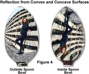
Spoons can be employed to simulate convex and concave mirrors, as illustrated in Figure 4 for the reflection of a young woman standing beside a wooden fence. When the image of the woman and fence are reflected from the outside bowl surface (convex) of the spoon, the image is upright, but distorted at the edges where the spoon curvature varies. In contrast, when the reverse side of the spoon (the inside bowl, or concave, surface) is utilized to reflect the scene, the image of the woman and fence are inverted.
| Interactive Java Tutorial | |||||||||||
|
|||||||||||
The reflection patterns obtained from both concave and convex mirrors are presented in Figure 5. The concave mirror has a reflection surface that curves inward, resembling a portion of the interior of a sphere. When light rays that are parallel to the principal or optical axis reflect from the surface of a concave mirror (in this case, light rays from the owl's feet), they converge on the focal point (red dot) in front of the mirror. The distance from the reflecting surface to the focal point is known as the mirror's focal length. The size of the image depends upon the distance of the object from the mirror and its position with respect to the mirror surface. In this case, the owl is placed away from the center of curvature and the reflected image is upside down and positioned between the mirror's center of curvature and its focal point.
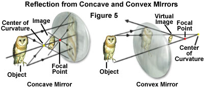
The convex mirror has a reflecting surface that curves outward, resembling a portion of the exterior of a sphere. Light rays parallel to the optical axis are reflected from the surface in a direction that diverges from the focal point, which is behind the mirror (Figure 5). Images formed with convex mirrors are always right side up and reduced in size. These images are also termed virtual images, because they occur where reflected rays appear to diverge from a focal point behind the mirror.
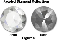
The manner in which gemstones are cut is one of the more aesthetically important and pleasing applications of the principles of light reflection. Particularly in the case of diamonds, the beauty and economic value of an individual stone is largely determined by the geometric relationships of the external faces (or facets) of the gem. The facets that are cut into a diamond are planned so that most of the light that falls on the front face of the stone is reflected back toward the observer (Figure 6). A portion of the light is reflected directly from the outside upper facets, but some enters the diamond, and after internal reflection, is reflected back out of the stone from the inside surfaces of the lower facets. These internal ray paths and multiple reflections are responsible for a diamond's sparkle, often referred to as its "fire". An interesting consequence of a perfectly cut stone is that it will show brilliant reflection when viewed from the front, but will look darker or dull from the back, as illustrated in Figure 6.
Light rays are reflected from mirrors at all angles from which they arrive. In certain other situations, however, light may only be reflected from some angles and not others, leading to a phenomenon known as total internal reflection. This can be illustrated by a situation in which a diver working below the surface of perfectly calm water shines a bright flashlight directly upward at the surface. If the light strikes the surface at right angles it continues directly out of the water as a vertical beam projected into the air. If the light's beam is directed at a slight angle to the surface, so that it impacts the surface at an oblique angle, the beam will emerge from the water, but will be bent by refraction toward the plane of the surface. The angle between the emerging beam and the surface of the water will be smaller than the angle between the light beam and the surface below the water.
If the diver continues to angle the light at more of a glancing angle to the surface, the beam rising out of the water will get closer and closer to the surface, until at some point it will be parallel to the surface. Because of light bending due to refraction, the emerging beam will become parallel to the surface before the light below the water has reached the same angle. The point at which the emerging beam becomes parallel to the surface occurs at the critical angle for water. If the light is angled still further, none of it will emerge. Instead of being refracted, all of the light will reflect at the water's surface back into the water just as it would at the surface of a mirror.
| Interactive Java Tutorial | |||||||||||
|
|||||||||||
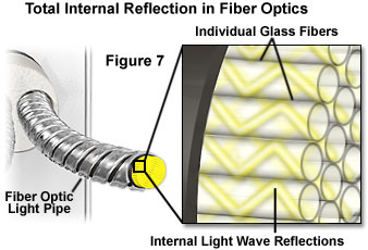
The principle of total internal reflection is the basis for fiber optic light transmission that makes possible medical procedures such as endoscopy, telephone voice transmissions encoded as light pulses, and devices such as fiber optic illuminators that are widely used in microscopy and other tasks requiring precision lighting effects. The prisms employed in binoculars and in single-lens reflex cameras also utilize total internal reflection to direct images through several 90-degree angles and into the user's eye. In the case of fiber optic transmission, light entering one end of the fiber is reflected internally numerous times from the wall of the fiber as it zigzags toward the other end, with none of the light escaping through the thin fiber walls. This method of "piping" light can be maintained for long distances and with numerous turns along the path of the fiber.
Total internal reflection is only possible under certain conditions. The light is required to travel in a medium that has relatively high refractive index, and this value must be higher than that of the surrounding medium. Water, glass, and many plastics are therefore suitable for use when they are surrounded by air. If the materials are chosen appropriately, reflections of the light inside the fiber or light pipe will occur at a shallow angle to the inner surface (see Figure 7), and all light will be totally contained within the pipe until it exits at the far end. At the entrance to the optic fiber, however, the light must strike the end at a high incidence angle in order to travel across the boundary and into the fiber.
The principles of reflection are exploited to great benefit in many optical instruments and devices, and this often includes the application of various mechanisms to reduce reflections from surfaces that take part in image formation. The concept behind antireflection technology is to control the light used in an optical device in such a manner that the light rays reflect from surfaces where it is intended and beneficial, and do not reflect away from surfaces where this would have a deleterious effect on the image being observed. One of the most significant advances made in modern lens design, whether for microscopes, cameras, or other optical devices, is the improvement in antireflection coating technology.
| Interactive Java Tutorial | |||||||||||
|
|||||||||||
Thin coatings of certain materials, when applied to lens surfaces, can help reduce unwanted reflections from the surfaces that can occur when light passes through a lens system. Modern lenses that are highly corrected for optical aberrations generally have multiple individual lenses, or lens elements, which are mechanically held together in a barrel or lens tube, and are more properly referred to as a lens or optical system. Each air-glass interface in such a system, if not coated to reduce reflections, can reflect between four and five percent of an incident light beam normal to the surface, resulting in a transmission value of 95 to 96 percent at normal incidence. Application of a quarter-wavelength thick antireflection coating having a specifically chosen refractive index can increase the transmission value by three to four percent.
Modern objective lenses for microscopes, as well as those designed for cameras and other optical devices, have become increasingly more sophisticated and complex, and may have 15 or more separate lens elements with multiple air-glass interfaces. If none of the elements were coated, reflection losses in the lens from axial rays alone would reduce transmittance values to around 50 percent. In the past, single-layer coatings were used to reduce glare and improve light transmission, but these have been largely supplanted by multilayer coatings that can produce transmittance values exceeding 99.9 percent for visible light.

Illustrated in Figure 8 is a schematic drawing of light waves reflecting from and/or passing through a lens element coated with two antireflection layers. The incident wave strikes the first layer (Layer A in Figure 8) at an angle, resulting in part of the light being reflected (R(0)) and part being transmitted through the first layer. Upon encountering the second antireflection layer (Layer B), another portion of the light (R(1)) is reflected at the same angle and interferes with light reflected from the first layer. Some of the remaining light waves continue on to the glass surface where they are again partially reflected and partially transmitted. Light that is reflected from the glass surface (R(2)) interferes (both constructively and destructively) with light reflected from the antireflection layers. The refractive indices of the antireflection layers differ from that of the glass and the surrounding medium (air), and are carefully chosen according to the composition of the glass used in the particular lens element to produce the desired refraction angles. As the light waves pass through the antireflection coatings and the glass lens surface, nearly all of the light (depending upon the angle of incidence) is ultimately transmitted through the lens element and focused to form an image.
Magnesium fluoride is one of many materials used for thin-layer optical antireflection coatings, although most microscope and lens manufacturers now produce their own proprietary coating formulations. The general result of these antireflection measures is a dramatic improvement of image quality in optical devices because of increased transmission of visible wavelengths, reduction of glare from unwanted reflections, and elimination of interference from unwanted wavelengths that lie outside the visible light spectral range.
The reflection of visible light is a property of the behavior of light that is fundamental in the function of all modern microscopes. Light is often reflected by one or more plane (or flat) mirrors within the microscope to direct the light path through lenses that form the virtual images we see in the oculars (eyepieces). Microscopes also make use of beamsplitters to allow some light to be reflected while simultaneously transmitting a portion of the light to different parts of the optical system. Other optical components in the microscope, such as specially designed prisms, filters, and lens coatings, also carry out their functions in forming the image with a crucial reliance on the phenomenon of light reflection.
Contributing Authors
Thomas J. Fellers and Michael W. Davidson - National High Magnetic Field Laboratory, 1800 East Paul Dirac Dr., The Florida State University, Tallahassee, Florida, 32310.