
Common Optical Defects in Lens Systems (Aberrations)
Microscopes and other optical instruments are commonly plagued by lens errors that distort the image by a variety of mechanisms associated with defects (commonly referred to as aberrations) resulting from the spherical geometry of lens surfaces. There are three primary sources of non-ideal lens action (errors) that are observed in the microscope.
Of the three major classes of lens errors, two are associated with the orientation of wavefronts and focal planes with respect to the microscope optical axis. These include on-axis lens errors such as chromatic and spherical aberration, and the major off-axis errors manifested as coma, astigmatism, and field curvature. A third class of aberrations, commonly seen in stereomicroscopes that have zoom lens systems, is geometrical distortion, which includes both barrel distortion and pincushion distortion.
In general, the ultimate effect of optical aberrations in the microscope is to induce faults in the tiny features and specimen detail of an image that is being observed or digitally recorded. Lens artifacts in the microscope were first addressed in the eighteenth century when the London instrument maker John Dollond discovered that chromatic aberrations could be reduced or eliminated by using a combination of two different types of glass in the fabrication of lenses. Several decades later, during the nineteenth century, achromatic (free of chromatic aberration) objectives with a high numerical aperture were developed, although there were still geometrical distortion problems with the lenses. Modern glass formulations and antireflective coatings, coupled to advanced grinding and manufacturing techniques, have all but eliminated a majority of the aberrations from today's microscope objectives. However, careful attention must still be paid to these artifacts, especially when conducting high-magnification digital microscopy or when working with stereomicroscopes that have zoom lens systems.
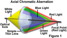
Chromatic Aberration - One of the most common faults observed in spherical lenses, chromatic aberration occurs because the lens refracts the various colors present in white light at a different angle according to the wavelength (see Figure 1). Red light is not refracted at the same angle as green or blue light so the focal point on the optical axis of the lens is farther away from the lens for red light. Likewise, green light is focused closer to the lens than red light, and blue light is focused in a plane that is closest to the lens. This phenomenon is commonly referred to as dispersion and occurs to a certain degree in all spherically shaped lens elements. The inability of the lens to bring all of the colors into a common focal plane results in a slightly different image size and focal point for each of the three predominant wavelength groups. The result is a colored fringe or halo surrounding the image, with the halo color changing as the focal point of the objective is varied.
| Interactive Tutorial |
|
||||||||||
|
|||||||||||
Chromatic aberration artifacts are compounded by the difference in image magnification that occurs as a result of the varying focal planes for each color group, an effect termed chromatic difference of magnification. Aberrations of this type can be significantly reduced, or eliminated, by making compound lenses that are composed of individual elements having different color-dispersing properties. A wide variety of optical glasses are now available to lens designers. For example, crown glass has dispersive properties that enable it to be paired in a lens doublet with a flint glass element to produce an achromatic doublet lens system that focuses blue and red wavelengths in the same image plane. Additional refinement of an optical system with even more sophisticated glass formulas and shapes can reduce chromatic aberration even further.
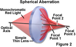
Spherical Aberration - A potentially serious artifact that can have serious consequences on images produced by the microscope, spherical aberration is the result of using lenses having spherical surfaces, which is currently the only practical approach to lens design. Spherical aberration occurs when light waves passing through the periphery of a lens are not brought into exact focus with those passing through the center (see Figure 2 for an example using monochromatic red light). The result is that a well-defined image plane does not exist, and the specimen cannot be correctly focused. As an example, a point source of light appears as a spot surrounded by a bright halo or series of diffraction rings when the microscope is brought into its "best" focus. Complex specimens that have a significant thickness are often so blurred as to be unrecognizable, especially at the periphery of the viewfield.
Correction of an optical system (such as a microscope) for spherical aberration is often accomplished by utilizing a combination of positive and negative lens elements with different thickness, which are cemented together to form a compound lens group. Spherical aberrations are very important in terms of the resolution of a lens because they affect the coincident imaging of points along the optical axis and degrade the performance of the lens, which will seriously affect specimen sharpness and clarity. These lens defects can frequently be reduced by limiting the outer edges of the lens from exposure to light using diaphragms, and also by utilizing aspherical lens surfaces within the optical system.
The highest-quality modern microscope objectives address spherical aberrations in a number of ways including special lens-grinding techniques, improved glass formulations, and better control of optical pathways. Objectives that are highly corrected for spherical aberration are often designed for specific conditions, such as strict cover glass thickness restrictions, oil immersion, and a narrow refractive index tolerance. Adjustable correction collars are available on some high-dry oil-free objectives to account for cover glass thickness variations. Microscope operators should carefully study the basic requirements of specialized objectives to make certain spherical aberration is not introduced due to utilization of the objective under conditions for which it was not designed.
Coma - Similar to spherical aberration in many respects, coma is generally encountered with off-axis light rays and is most severe when the microscope is out of proper alignment. The aberration is named for its strong resemblance to the shape of a comet tail, and is manifested by a streak of light that appears to emanate from a focused spot at the periphery of the viewfield. Coma is often considered the most problematic aberration due to the asymmetry it produces in images. It is also one of the easiest aberrations to demonstrate. For example, on a bright, sunny day, when a magnifying glass is used to focus an image of the sun on the sidewalk, coma aberration can be seen in the image when the magnifying glass is tilted with respect to the principal rays from the sun. The sun's image, when projected onto the concrete, will elongate into a comet-like shape that is characteristic of coma aberration.
| Interactive Tutorial |
|
||||||||||
|
|||||||||||
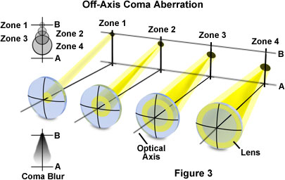
The distinct shape displayed by images suffering from coma aberration is the result of refraction differences by light rays passing through the various lens zones as the incident angle becomes more oblique (off-axis). The severity of comatic aberration is a function of thin lens shape. In the extreme, coma results in meridional rays passing through the periphery of the lens to arrive at the image plane closer to the axis than do light rays passing through the central portion of the lens (and closer to the principal ray, as illustrated in Figure 3). In this case, the peripheral rays produce the smallest image and the coma aberration is said to be negative. In contrast, when the peripheral rays are focused farther down the axis to produce a much larger image, the aberration is termed positive. The "comet" shape may have its "tail" pointing toward the center of the viewfield or away, depending upon whether the aberration has a negative or positive value, respectively. The degree of coma aberration is greater for lenses with wider apertures, and can be corrected (in part) by reducing aperture size. Microscope designers usually attempt to correct coma aberration to accommodate the diameter of the object field for a given objective and eyepiece combination.
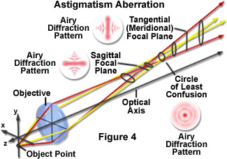
Astigmatism - Astigmatism aberration is similar to coma; however, this artifact is not as sensitive to aperture size and depends more strongly on the oblique angle of the light beam. The aberration is manifested by the off-axis image of a specimen point appearing as a line or ellipse instead of a discrete point. Depending on the angle of the off-axis light rays entering the lens, the line image may be oriented in either of two different directions (see Figure 4), tangentially (meridionally) or sagitally (equatorially). The intensity ratio of the unit image will diminish, with definition, detail, and contrast being lost as the distance from the center is increased.
In less expensive microscopes, astigmatism is often the result of asymmetric lens curvature due to mistakes in manufacture or improper mounting of a lens in its frame or orientation within the objective barrel. Astigmatism lens errors are usually corrected by designing microscope objectives to provide precise spacing of individual lens elements as well as appropriate lens shapes and refractive indices. Careful alignment and adjustment of the individual lens elements is accomplished with spacers and shims to reduce or eliminate the effects of astigmatism.
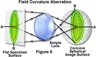
Field Curvature - Also commonly referred to as curvature of field, this aberration, which is the natural result of employing lenses that have curved surfaces, is very familiar to many experienced microscopists. When light is focused through a curved lens, the image plane produced by that lens will be curved, as illustrated in Figure 5. The image can be focused over the range between points A and B to produce a sharp focus either on the edges or in the center. Categorized as an off-axis aberration, field curvature produces an image plane having the shape of a concave spherical surface (resembling a convex lens surface), as seen from the objective. Although successive zones can be brought into focus by translating the objective, the entire image cannot be simultaneously focused onto a flat surface such as a film plane or the surface of a CCD or CMOS image sensor.
| Interactive Tutorial |
|
||||||||||
|
|||||||||||
Optical designers deal with field curvature by adding corrective lens elements to the objective in specially designed flat-field objectives. Although the optical correction for field curvature requires the addition of several new lenses to the design, these objectives (termed plan or plano) are the most common type of objective in use today. Field curvature is seldom totally eliminated, but it is often difficult to detect edge curvature with most plan-corrected objectives. As a result, very limited degrees of field curvature often do not degrade photomicrographs or digital images. The artifact is more severe at low magnifications and can be a serious problem with stereomicroscopes.
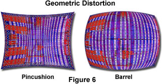
Geometrical Distortion - Image distortion is an aberration commonly observed in stereomicroscopy, and is manifested by changes in the shape of an image rather than the sharpness or color spectrum. The two most prevalent types of geometrical distortion, positive and negative (often termed pincushion and barrel, respectively), can often be present in very sharp images that are otherwise well-corrected for spherical and chromatic aberrations, as well as coma and astigmatism. When images suffer from distortion, the true geometry of a specimen is no longer maintained in the image. Figure 6 illustrates examples of rather significant pincushion and barrel distortion in the image of a computer microprocessor integrated circuit.
Geometric distortion can be difficult to detect, especially when the aberration is relatively slight and the specimen lacks periodic structures. This type of artifact is most severe in specimens that have straight lines, such as periodic grids, squares, rectangles or other regular polygonal features that readily show the curvature present from distortion. Distortion is often found in optical designs utilizing compound lens systems (telephoto, fisheye, and zoom) containing meniscus, concave, hemispherical, and thick convex lenses. Complex lens systems, such as the zoom design, can have rather pronounced distortion, which may vary with focal length, producing pincushion distortion at long focal lengths and barrel distortion at short focal lengths. For this reason, stereoscopic zoom microscopes classically have a significant amount of distortion present and microscope manufacturers have expended considerable effort in alleviating this aberration.
Contributing Authors
Mortimer Abramowitz - Olympus America, Inc., Two Corporate Center Drive., Melville, New York, 11747.
Kenneth R. Spring - Scientific Consultant, Lusby, Maryland, 20657.
Michael W. Davidson - National High Magnetic Field Laboratory, 1800 East Paul Dirac Dr., The Florida State University, Tallahassee, Florida, 32310.
BACK TO LENSES AND GEOMETRICAL OPTICS