
Interactive Java Tutorials
Image Formation with Diverging Lenses
Negative lenses diverge parallel incident light rays and form a virtual image by extending traces of the light rays passing through the lens to a focal point behind the lens. In general, these lenses have at least one concave surface and are thinner in the center than at the edges. This interactive tutorial utilizes ray traces to explore how images are formed by the three primary types of diverging lenses, and the relationship between the object and the image formed by the lens as a function of distance between the object and the focal points.
The tutorial initializes with an object (represented by the larger vertical gray arrow on the far left-hand side of the lens) positioned approximately twice the distance of the focal length away from a simple thin bi-concave lens. Ray traces emanating from the point of the object arrow (Object) pass through various points on the lens and are diverged away from ray extensions traced back to the focal point (F). Three of the rays are illustrated in red: the Principal Ray, which passes through the center of the lens, and two additional characteristic rays. One of the characteristic rays travels towards the lens rear focal point (F'), but is diverted in a direction parallel to the Optical Axis after passing through the lens. The other characteristic ray travels toward the lens parallel to the optical axis and diverges sharply away from the axis after passing through the lens. Extensions drawn from any two of these three rays can be utilized to determine the size and placement of the Virtual Image formed by the lens.
In order to operate the tutorial, use the Object Position slider to translate the object arrow back and forth along the optical axis of the lens. As the object is moved closer to the lens, the virtual image size increases and also moves closer to the lens. In a similar manner, as the object is moved away from the lens, the virtual image moves away from the lens and grows smaller. The distance between the lens and the object (Object Distance, (p)) and image (Image Distance, (q)) are continuously updated in the lower left-hand corner of the tutorial window. The bi-concave lens can be changed to either a Negative Meniscus or Plano-Concave element by selecting the appropriate choice using the pull-down menu.
When a negative lens is placed between an object and the eye, it does not form a real image, but reduces (or demagnifies) the apparent size of the object by forming a virtual image. The distinction between a real and a virtual image is an important concept when imaging specimens through a lens or mirror system, regardless of whether the system consists of a single or multiple components. In general, images are defined by the regions where light rays (and their extensions) become convergent as the result of refraction by a lens or reflection by a mirror. In cases where the light rays intersect at a focal point, the image is real and can be viewed on a screen, recorded on film, or projected onto the surface of a sensor such as a CCD or CMOS placed in the image plane. When the light rays diverge, but project imaginary extensions that converge to a focal point, the image is virtual and cannot be viewed on a screen or recorded on film. In order to be visualized, a real image must be formed on the retina of the eye. When viewing specimens through the eyepieces of a microscope, a real image is formed on the retina, but it is actually perceived by the observer to exist as a virtual image located approximately 10 inches (25 centimeters) in front of the eye.
Negative lens elements are the bi-concave (Figure 1(a)), plano-concave (Figure 1(b); with a single planar surface), and concave-meniscus (also termed a negative meniscus lens; Figure 1(c)), which also has concave and convex surfaces, but with the center of the lens being thinner than the edges. For both positive and negative meniscus lenses, the distances between the surfaces and their focal planes are unequal, but their focal lengths are equal. The line passing through the center of the lens curved surfaces in Figure 1(a) is known as the optical axis of the lens. Simple lenses having a symmetrical shape (bi-convex or bi-concave) have principal planes that are equally spaced with respect to each other and the lens surfaces. The lack of symmetry in other lenses, such as the meniscus lenses and the plano negative and positive lenses, causes the locations of the principal planes to vary according to lens geometry. Plano-convex and plano-concave lenses have one principal plane that intersects the optical axis, at the edge of the curved surface, and the other plane buried inside the glass. The principal planes for meniscus lenses lie outside the lens surfaces.
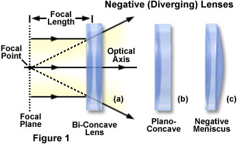
Bi-concave lenses (Figure 1(a)) are primarily utilized for diverging light beams and image size reduction, as well as increasing optical system focal lengths and collimating converging light beams. Often termed the double-concave lens, this optical element refracts parallel input rays so that they diverge away from the optical axis on the output side of the lens, forming a negative focal point in front of the lens. Although the output light rays do not actually unite to form a focal point, they do appear to be diverging from a virtual image located on the object side of the lens. Bi-concave lenses can be coupled to other lenses to reduce optical system focal lengths.
The plano-concave lens illustrated in Figure 1(b) is a divergent element that has a negative focal point and produces a virtual image. When a collimated light beam is incident on the curved surface of a plano-concave lens element, the exit side will form a divergent beam. This beam will appear to emerge from a smaller virtual point source than if the planar lens surface had faced the collimated light beam. Plano-concave lenses, which feature minimal spherical aberration when the concave surface is facing the longest conjugate distance, are employed to expand light beams or to increase focal lengths in existing optical systems.
Also referred to as a convexo-concave lens, the negative (divergent) meniscus lens (Figure 1(c)) can be designed to reduce or eliminate additional spherical aberration or coma in optical systems to which the lens is coupled. Meniscus lenses (both positive and negative) are often employed to shorten the focal length of a doublet (two lens elements cemented together) or a plano-convex lens operating at an infinite conjugate ratio (illuminated by parallel light rays). The desired focal length of the final system determines the particular dimensions and character of the meniscus lens that should be added. Plano-convex/meniscus lens combinations display up to four times greater resolution than a plano-convex lens working alone.
Contributing Authors
Matthew J. Parry-Hill, Robert T. Sutter and Michael W. Davidson - National High Magnetic Field Laboratory, 1800 East Paul Dirac Dr., The Florida State University, Tallahassee, Florida, 32310.
BACK TO LENSES AND GEOMETRICAL OPTICS