
Digital Image Capture and Processing
Interface Software Capture Window
After the MIC-D digital microscope software has been installed, the setup routine creates a desktop shortcut (consisting of a small microscope icon labeled MIC-D) to the executable program file. Double clicking on this icon will launch and initialize the microscope interface software. During initialization, a splash screen briefly appears to alert the operator with information about the software version and some general copyright information.
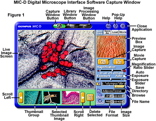
Prior to initialization of the image capture window, a dialog box appears to query the operator with the image capture size requirement, providing a pull-down menu choice of either 640 x 480 or 320 x 240 pixels. The default (and recommended) capture size is 640 x 480 pixels, but in order to conserve computer resources and storage space, operators can choose the smaller image format. When the image size has been selected, the software initializes the CMOS image sensor and launches the image capture window, illustrated in Figure 1. This window contains all of the software controls necessary to capture still images, time-lapse sequences, and full-motion video sequences. The default setting upon initialization is single image capture at 640 x 480 pixels, with JPEG compression format for storage, and automatic exposure.
Microscope illumination is controlled thorough a potentiometer housed on the base, which can be utilized to turn on the light emitting diode (LED) lamp and vary the voltage to adjust and control lamp intensity. If the microscope lamp is activated and a specimen is placed on the stage, an image will appear in the Live Image Screen (see Figure 1). This screen displays the live video feed from the CMOS Active Pixel Sensor digital imaging circuitry housed within the MIC-D microscope body. The video display illustrated in the Live Image Screen (Figure 1) is a fat-stained thin section of adipose tissue imaged in brightfield illumination mode.
In most cases, when the software is initialized and the microscope lamp is on, the video feed displays an image that is usually a blurred and out-of-focus rendition of the specimen positioned on the microscope stage. The microscope zoom handle control can be rotated to increase or decrease the magnification of the specimen image, and the focus control (positioned near the stage) is used to bring the specimen into sharp focus. Provided the illuminator is positioned on-axis, in brightfield observation mode, the automatic exposure control in the software should ensure that the specimen image visible in the Live Image Screen window has a satisfactory brightness level.
Specimens should always be images at the MIC-D microscope's lowest zoom handle setting. It may require some practice to correctly position and focus specimens so that they appear sharp and crisp in the Live Image Screen. In addition, there will usually be a delay between twisting the focus knob and the response of the image on the screen. It is important to make very small incremental changes to the focus knob, and then wait a second or two until the video feed stabilizes. Always attempt to slowly "squeeze" the microscope into focus instead of moving the knob in rapid jerks. Finding the correct focus will become increasing more difficult at the extremes of the zoom magnification range (both high and low). Light intensity also tends to drop when increasing the magnification, but this is partially compensated by a potentiometer geared to the zoom shaft, which automatically adjusts the CMOS image sensor gain as the magnification is increased and decreased.
Live video response time is a function with several variables. The most important factor is the quality and speed of the host computer's video system. Video cards having advanced Accelerated Graphics Port (AGP) bus will respond much more efficiently than those using older Peripheral Component Interconnect (PCI) bus systems. Also, the size of on-board video random access memory (RAM) and the video card's random access memory digital-to-analog converter (RAMDAC) chip clock speed will affect the host computer's refresh rate and video response, and thus the MIC-D microscope response time. These hardware variables are a function of the host computer architecture and nothing can be done to improve performance short of a hardware upgrade.
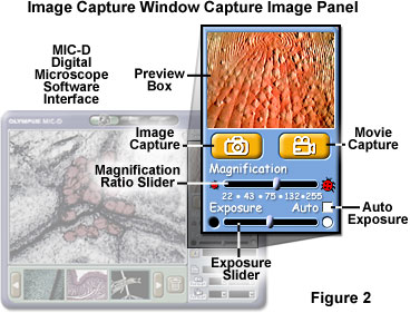
The Capture Image panel, illustrated in Figure 2, is utilized to make exposure adjustments, adjust the Magnification Ratio slider, and to capture single images or full-motion video sequences. In addition, the Preview Box, which appears directly above the Image Capture and Movie Capture buttons, contains the last image captured by the software. This is the image that will be transferred (by default) into the image processing window when the capture window is exited by clicking on the Image Processing Window button. The Magnification Ratio slider should be adjusted to a position that corresponds to the numerical magnification ratio imprinted on the microscope base beneath the zoom handle control. Translating this slider also produces a change in the size of the magnification scale superimposed onto the image in the Live Image screen. Correct use of the Magnification Ratio slider will ensure that approximate magnification scales are recorded with each image.
The values indicated beneath the Magnification Ratio slider have been calculated assuming that the host computer monitor has a pixel size of 0.3 millimeters and the display settings are set to a high monitor resolution (1024 x 768 pixels). As a consequence, the size and resolution of the monitor may alter the values indicated by the index on the slider and may differ from the actual observed magnification. In order to compensate for monitors that vary significantly from the recommended specifications, the operator must measure the length of the scale bar displayed in the Live Image Screen with a ruler and divide the actual measured scale length by the length indicated adjacent to the scale (on the screen) to obtain the approximate magnification size.
The microscope interface software is capable of capturing images of similar size, regardless of the host computer screen resolution. In effect, when the computer monitor is set to a screen resolution of 640 x 480, images captured with the software are identical to those obtained when the screen resolution is 1600 x 1200 (and the same holds for all resolutions in between). Changing the color depth of the host computer also does not affect the color resolution of images captured by the software, which remain at 8-bits per channel (true color) in red, green, and blue (RGB) color space mode. Therefore, when the host computer monitor is set to a resolution of 640 x 480 x 256 colors (indexed color), images captured by the MIC-D software are identical to those captured with a monitor resolution of 1600 x 1200 x 24-bit color. In fact, at the lowest screen resolutions, images captured by the microscope software far exceed the quality of those displayed in the Live Image Screen on the host computer monitor.
Upon software initialization, the exposure control is set to Auto Exposure with a checkmark placed in the Auto checkbox, which is positioned directly above the Exposure slider. The operator can adjust exposure manually by deselecting the checkbox and using the slider to control exposure. Moving the slider to the left (closer to the black circle) decreases exposure (CMOS image sensor integration) time, while translating the slider to the right (closer to the white circle) increases the amount of integration time. As the microscope magnification is increased, the exposure slider must be continually moved to the right to compensate for reduced image intensity. At the highest magnifications, the slider is often positioned at the extreme right-hand range limit. Note that the Exposure slider does not change the lamp voltage on the microscope, but only adjusts the gain on the CMOS image sensor. Translating the slider to the right increases image sensor gain, while moving the slider to the left decreases the gain.
Before capturing images, the operator should select a folder or directory in which to store the image files. The default location (chosen by the software) is in the program directory on the computer's system (C:) drive:
Sequential images are stored as JPEG (Joint Photographic Experts Group) files by default with the prefix Img followed by an appending number that starts with 001 and advances either to 999, until the session is terminated, or the operator changes the image prefix name. Associated with each single image, and also stored by default in the ..\Def directory, is a *.dat file that contains important information about the image, including the storage directory, file name, time and date recorded, and the magnification scale size. The Capture Image controls are actually part of a settings panel series labeled with the tabs that include Auto Save, which refers to the automatic file saving routine illustrated in Figure 3. Other settings panels, discussed below, are Save As, Load, and Movie, which are utilized to configure specialized file storage locations for individual image files, to load new images into the Preview Box, and to configure full-motion video and time-lapse capture parameters.
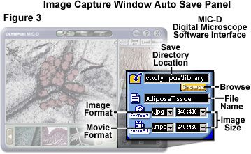
The Auto Save settings panel is employed to select a directory to automatically save images as they are captured, and to specify image names, file types, and capture sizes for both individual images and for time-lapse movies. In order to automatically save images into a specific directory, either type the path into the Save Directory text input box (see Figures 1 and 3), or use the Browse button located beneath the box to follow the Windows directory tree to the target directory. After the appropriate directory has been selected, type a file name prefix in the File Name text input box. Each time a new image is saved, it will be stored in the selected directory (along with the associated *.dat file) with the specified file name prefix, followed by a number starting with 001. These variables can be changed at any time during an imaging session.
Also specified in the Auto Save settings panel are the image file storage format selections (JPEG, TIFF, or BMP) for single digital images. Time-lapse and full-motion video sequences can be saved in either MPEG (Moving Picture Experts Group) or audiovisual (AVI) file formats. These are selected through pull-down menus (Figure 3), as are the image pixel sizes (640 x 480 or 320 x 240) for all capture and storage formats. Single images captured and stored in JPEG format range in size from about 80 to 450 kilobytes, depending upon the pixel dimensions, number of colors, and spatial detail present in the image. Uncompressed TIFF and BMP files are about three times the size of the JPEG compressed images. Time-lapse and full-motion video sequence files are not limited in size by the software and can range up to hundreds of megabytes in size. However, the latter are restricted by the hard drive space available on the host computer.
When the microscope is properly adjusted and the correct Auto Save and Capture Image settings panel parameters are set, the software is ready to start acquiring images. Use the mouse cursor to depress the Image Capture button for single digital images and the Movie Capture button to record full-motion video sequences. Depressing the yellow Movie Capture button turns this button to a red recording button with the camera icon positioned behind the standard parallel stop bars that are universally employed to indicate termination of a recording session.
Time-lapse and full-motion video sequences are automatically stored with an associated *.thm data file that contains image information necessary for displaying a thumbnail image of the video sequence in the Thumbnail Image panel. Captured single images and the first frame of full-motion video sequences appear in both the Preview Box and the far right-hand frame of the Thumbnail Image panel. If the image appearing in these display windows is the first image of a video or time-lapse sequence, then a small movie camera icon is positioned in the lower right-hand corner of the image. In addition, the image appearing in the Thumbnail Image panel is selected by a light blue (cyan) bounding box surrounding the periphery.
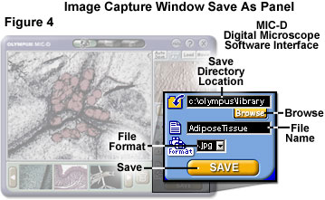
The Save As settings panel can be accessed by clicking on the appropriately labeled tab above the Preview Box in the image capture window. This configuration panel can be utilized to save specific images at any time during an imaging session, or to convert a still image or video sequence previously captured into another file format. Single images, regardless of the captured file format specification, can be converted into JPEG, TIFF, or BMP format using the Save As settings panel. However, a video sequence can only be converted from AVI format to MPEG format using this panel. Note that it is not possible to save a single image in a video sequence format (AVI or MPEG), nor is it possible to save a video sequence in a single image format (TIFF, JPEG, or BMP).
After the Save As panel tab has been selected, the settings panel illustrated in Figure 4 is presented beneath the exposure slider. Upon initialization, the Save As panel default directory for file storage is the same as that for the Auto Save panel, and resides in the program file directory on the host computer system drive (see the directory tree listed above). To specify a custom directory, click on the Browse button and select the target directory from the Windows directory tree listing. Alternatively, the file path can be input directly into the Save Directory text box by clicking within the box and manually typing the path sequence. Next, enter a file name (there is none by default) into the File Name text input box. The file storage format can then be selected using the File Format pull-down menu. Choices include JPEG, TIFF, BMP, MPEG, and AVI. Note that, in addition to single image files, video and time-lapse sequences can be saved with different file names and into new locations with the Save As settings panel. Finally, clicking on the Save button, located beneath the File Format pull-down menu, will save the image in the specified location.
Launching the Save As settings panel does not affect the sequential storage location for captured single or sequential (movie and time-lapse) images, which may have been previously established in the Auto Save settings panel. In addition, when the Save As panel is displayed, single images and sequences can still be captured and saved to the location specified by the Auto Save settings panel by clicking on the Image Capture or Movie Capture buttons. However, the specified Auto Save directory, file name prefix, and image storage format are not accessible when the Save As settings panel is displayed. In order to access these parameters, use the mouse cursor to click on the Auto Save tab above the Preview Box window.
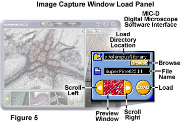
Digital images previously recorded in another session or images from other sources may be loaded into the MIC-D interface software capture window using the Load settings panel (provided they have the associated *.dat files). To access this menu, click on the Load tab positioned above the Preview Box in the capture window (see Figure 5). When the Load panel initializes, the default director is the same as that described above for the Auto Save and Save As settings panels in the program directory on the system drive. The Browse button can be utilized to scan the Windows directory tree for a specific location from which to load files. The directory path can also be typed directly into the Load Directory text input box. After the appropriate directory has been selected, any JPEG, TIFF, or BMP files stored in the directory can be displayed and scrolled in alphabetical order (by file name) through the Preview Window (see Figure 5). Positioned to the left and right of this window are scroll buttons that enable the operator to page through the images in the selected directory.
When a selected image appears in the Preview Window, it can be loaded into the Preview Box, bumping the last captured image to the Thumbnail Group (see Figure 1), by clicking on the Load button. If desired, the entire contents of the selected directory can be loaded into the Preview Box and Thumbnail Group with the Load feature. As each new image is loaded, it bumps the previously loaded image to the next position in the Thumbnail Group. Images from several directories can be loaded by this mechanism by changing the target load directory in the Load Directory location input box.
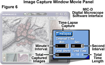
Adjacent to the Load settings panel tab is a tab entitled Movie, which displays the Time-Lapse settings panel illustrated in Figure 6. This panel is utilized to configure the software to collect digital video sequences in timed intervals. In order to set the time-lapse capture parameters, use the Minute Interval pull-down menu to select the number of elapsed minutes between successive image captures. The allowed range is from 0 to 60 minutes. Next, select the number of seconds to be added to the total number of minutes, between a range of 0 and 59 seconds, using the Seconds Interval pull-down menu. These two values are added together to arrive at the target time interval. For example, in Figure 6, the Minute Interval box is shown with 1 minute selected, and the Second Interval menu selection is 30 seconds for a total interval time of one minute and 30 seconds.
After the interval period has been selected, type the total number of images to be captured in the Total Shots (or Total Captured Images) text input box. This input box does not have a pull-down menu, so the value must be input from the keyboard. The software automatically calculates the total time necessary to complete the sequence and displays this value in hours, minutes, and seconds beneath the Total Time text line, adjacent to the Total Shots text input box. To initiate capture of time-lapse sequences, click on the Timelapse button in this settings panel. The target storage directory, file name prefix, and storage format must have been previously selected using the Auto Save settings panel. When the Timelapse button is activated, it turns red in color, then back to blue upon deactivation and premature termination of the capture sequence.
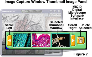
As images are captured, they first appear simultaneously in the Preview Box and the far right-hand position in the Thumbnail Image panel (Figure 7). Single images appear as miniature versions of the full-frame image, but time-lapse and full-motion video sequences have a small movie camera icon positioned in the lower right-hand corner of the image to indicate the file is an AVI or MPEG format. When an image (single or sequence) first appears in the Thumbnail Image panel, it is surrounded by a blue bounding box that indicates the image is selected. The selected image can be transferred from the Thumbnail Image panel to the Preview Box by double clicking directly on the image.
When the number of images captured in a session exceeds the number of frames in the Thumbnail Image panel (3 frames), the yellow Scroll buttons can be utilized to toggle images in the collection back and forth in the miniature windows. Clicking on the Scroll Left button (see Figure 7) reviews previously captured images by replacing the image in the far left-hand window by last captured image, at the rate of one image per click. Activating image translation in the Thumbnail Image panel removes the blue selection boundary, so that no specific image is then selected. Images can be scrolled until the first image captured in a session is displayed in the left-hand window of the Thumbnail Image panel. Unwanted images (or video sequences) can be deleted by first selecting them with a single click and then clicking on the yellow Delete button containing a trash can icon.
Navigational buttons positioned in the upper portion of the software interface Capture Window can be utilized to launch the Library Window, Image Processing Window, or to obtain help and close the application (see Figure 1). The Capture Window button contains a small single-lens reflex camera icon, and is highlighted with a green background when this window is open. When the mouse cursor is rolled over the Library Window button or the Image Processing Window button, the buttons acquire a green background and the icon becomes highlighted. The Library Window icon resembles a photograph album, while the icon on the Image Processing Window represents a paint palette and paintbrush.
Positioned in the upper right-hand corner of the Capture Window are three round buttons containing either the word Help, a question mark, and an X symbol. Clicking on the Help button launches the Windows program help files associated with the MIC-D digital microscope hardware and software (the Help button will turn yellow when the mouse cursor rolls over). This program contains a directory tree with information about all aspects of the microscope, including a section dedicated to the Capture Window, and should be used for obtaining information about the basic operating procedures and troubleshooting.
The question mark button, which turns green when the mouse cursor rolls over, launches Pop-Up help screens that enable the operator to determine the function of various software features. Clicking on the button changes the cursor into a question mark and arrow pointer, which can then be placed over a button, text box, window, or other area of interest to determine the function. Clicking on the area of interest while the software is in Pop-Up help mode will display a small text dialog box that explains the function of the particular software component.
Clicking on the Close Application button (see Figure 1) will terminate the software interface program instance. When the mouse cursor rolls over this button, it turns red to alert the operator that program termination will commence upon clicking. If images have been captured in the default folder (in the program directory on the system drive) during the software session, the program queries the operator with a message warning that these files will be deleted during the next software session and asks whether the software should be closed. If the operator clicks on the No button in response to this query, the software does not exit. However, if the operator clicks on the Yes button, then the software will terminate without removing the image files from the default directory. During the next software launch instance, a dialog box appears to determine whether the operator wants to delete the files remaining in the default storage directory.
Contributing Authors
Thomas J. Fellers and Michael W. Davidson - National High Magnetic Field Laboratory, 1800 East Paul Dirac Dr., The Florida State University, Tallahassee, Florida, 32310.
BACK TO DIGITAL IMAGE CAPTURE AND PROCESSING
BACK TO THE OLYMPUS MIC-D DIGITAL MICROSCOPE
Questions or comments? Send us an email.
© 1995-2025 by Michael W. Davidson and The Florida State University. All Rights Reserved. No images, graphics, software, scripts, or applets may be reproduced or used in any manner without permission from the copyright holders. Use of this website means you agree to all of the Legal Terms and Conditions set forth by the owners.
This website is maintained by our
Graphics & Web Programming Team
in collaboration with Optical Microscopy at the
National High Magnetic Field Laboratory.
Last Modification Friday, Nov 13, 2015 at 02:19 PM
Access Count Since September 17, 2002: 18510
Visit the website of our partner in introductory microscopy education:
|
|