
Anatomy of the MIC-D Digital Microscope
Reflected Illumination Mode
In general terms, the world of optical microscopy can be largely divided into two main categories: transmitted light microscopy and reflected light microscopy. Transmitted light microscopy is utilized for specimens that are relatively thin and semi-transparent, enabling a significant amount of light to pass through. In contrast, reflected light microscopy, often termed incident light or metallurgical microscopy, is reserved for those specimens that remain opaque even when ground to a thickness of 30 micrometers or less.
The range of specimens falling into the reflected or incident light category is enormous, and includes metals, ores, ceramics, polymers, semiconductor wafers and dies, slag, coal, plastics, paint, paper, wood, leather, and glass inclusions. In order to study these specimens, which are unable to pass light through the interior, illumination must be directed onto the surface and eventually returned to the microscope objective by either specular of diffused reflectance. This type of illumination is often referred to as episcopic illumination, epi-illumination, or vertical illumination (in effect, from above) as contrasted to diascopic illumination (transmitted light). A variety of microscope configurations, including that of the Olympus MIC-D digital microscope, enable the operator to alternate or simultaneously conduct investigations in reflected and transmitted illumination. Because reflected light microscopy has a large number of industrial applications, this form of illumination represents a very important segment of all microscopical studies.
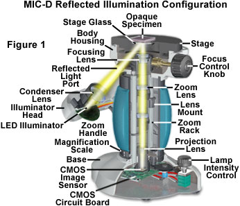
Presented in Figure 1 is the recommended configuration of the MIC-D digital microscope for reflected light illumination. The rotation arm is translated from the on-axis (vertical) position through a 135-degree angle to direct light onto the surface of a specimen, at an incident illumination angle of 45 degrees, by means of a port located beneath the stage. In this configuration, the illumination head is not rotated from its default position (coaxial with the rotation arm) on the pivot that secures it to the rotation arm. Correct positioning of the rotation arm is guaranteed by a pin attached to the backside of the arm adjacent to the microscope body. The pin rests in a crescent-shaped cavity that defines the range of motion allowed for the rotation arm. When the pin is firmly seated at one end of the cavity, the rotation arm resides in a vertical position for brightfield microscopy, while at the other end, the rotation arm is oriented for reflected light microscopy. Within a 25-degree range of the brightfield position, the pin has freedom to move so that the rotation arm can be utilized to obliquely illuminate the specimen.
| Interactive Tutorial | |||||||||||
|
|||||||||||
In reflected light illumination mode, the diffusion screen, located within the illumination head, should be removed from the optical pathway to alter light distribution from the light-emitting diode (LED) source and project a more concentrated light beam through the lower microscope port and onto the specimen. When the diffusion screen is utilized to spread light from the LED light source, the overall intensity of light reaching the specimen is often not enough to produce a visible image. In addition, under conditions of very low light, the CMOS image sensor will produce images that contain a significant amount of noise.
Because the MIC-D digital microscope is configured to perform in critical (or source focused) illumination in all imaging modes, the instrument is not equipped with a field or condenser aperture diaphragm. A majority of the research-level reflected light microscopes operate in K�hler illumination using both field and aperture diaphragms, with the objective serving a dual role as a condenser and the primary imaging element. The function of K�hler illumination (aside from providing evenly distributed illumination) is to ensure that the objective will be able to deliver excellent resolution and good contrast even if the source of light is a coil filament lamp. In critical illumination, the source (a white light LED in the MIC-D microscope) is focused onto the specimen, usually through a diffusion filter. The numerical aperture of the MIC-D condenser lens element is approximately 0.20, which is sufficient to fully illuminate the aperture of the objective (numerical aperture equal to 0.05 to 0.17) throughout the zoom magnification range.
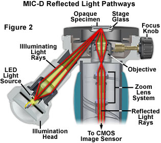
Ray traces of light passing through the MIC-D optical train in reflected light illumination mode are presented in Figure 2. Light from the LED source is focused by the condenser lens element to form a cone of illuminating rays that enter the microscope through the lower port. These light rays then pass through the stage glass and are incident on the specimen at an angle of 45 degrees. Depending upon the specimen texture (specular or diffuse) light is then reflected or scattered back through the stage glass and into the objective front lens. The microscope is focused by translating the rear objective lens position with respect to the front lens, which is housed in a fixed location in the microscopy body. Light focused by the objective next enters the front lens of the zoom system and passes through the remainder of the optical system to the projection lens and the CMOS image sensor.
When light from the illumination system enters the MIC-D microscope lower port, the first surface it encounters is the glass plate housed in the stage aperture. The intensity of light impacting the specimen is determined by the angle of incidence and refractive index of the glass stage, but in all cases, some of the light will be reflected away from the glass surface without passing through to the specimen. Because the incident angle in the MIC-D reflected light mode is 45 degrees, the percentage of partially reflected light (away from the specimen) would be about 12-15 percent for a glass plate having a refractive index of 1.5 and lacking anti-reflection coatings on the surface. After reflecting (or scattering) from the surface of the specimen, the light must again pass through a glass-air interface and undergo reflection losses before entering the microscope lens system. The net effect of these reflection losses is a severe reduction in image contrast and the production of ghost images due to second surface reflection.
Reflection at the interface between a glass plate (or lens) and air can be reduced through the application of antireflection coatings to the surface of the glass. Thin coatings of specialized materials can be applied to lens and glass surfaces to help reduce unwanted reflections that occur when light passes through. Modern microscope lens systems are highly corrected for optical aberrations, and generally have multiple individual lens elements that are mechanically held together in a barrel or lens tube. Each glass-air interface, if not coated to reduce reflections, can reflect between four and five percent of an incident light beam normal (perpendicular) to the surface, resulting in a transmission value of 95 to 96 percent at normal incidence. Application of a quarter-wavelength thick antireflection coating having a specifically chosen refractive index can increase the transmission value by three to four percent.
Magnesium fluoride is one of many materials used for thin-layer optical antireflection coatings, although most microscope and lens manufacturers now produce their own proprietary coating formulations. The general result of these antireflection measures is a dramatic improvement of image quality in optical devices because of increased transmission of visible wavelengths, reduction of glare from first and second surface reflections, and elimination of interference from shorter and longer wavelengths that lie outside the visible light spectral range.
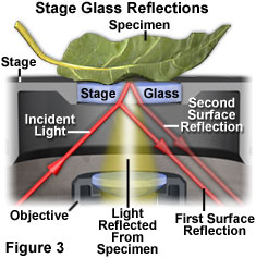
Illustrated in Figure 3 is a close-up view of incident illumination striking the stage glass plate in the MIC-D microscope (red arrow). Light rays strike the plate at a 45-degree angle and a portion of the beam is reflected at the same angle into the interior of the microscope body, never reaching the specimen or optical train of the microscope (labeled first surface reflections). Some of the light passes through the glass plate and is reflected away from the second surface of the plate back into the microscope body. However, a portion of the light rays incident on the stage plate pass through to the specimen, where they are reflected and scattered through a wide spectrum of angles. Those rays that are reflected (or scattered) at a 45-degree angle with respect to the incident illumination will pass through the stage glass parallel (or nearly so) to the microscope optical axis and enter the microscope objective front lens. In Figure 3 the light rays reflected by the specimen into the microscope objective are depicted as a yellow beam of light (light reflected by the specimen in other directions is omitted). Because of surface reflections, a majority of the specimens targeted for imaging under reflected light conditions are prepared without a glass coverslip.
Modern objective lenses for microscopes have become increasingly more sophisticated and complex, and may have 15 or more separate lens elements with many air-glass interfaces. In addition most microscopes have accessory glass components, such as windows, mirrors, and filters, which are located in strategic positions within the optical train. If none of the elements were coated, reflection losses in the lens for axial rays alone would reduce transmittance values to around 50 percent (or greater). In the past, single-layer coatings were used to reduce glare and improve light transmission, but these have been largely supplanted by multilayer coatings that can produce transmittance values exceeding 99.9 percent for visible light.
The stage glass plate on the MIC-D microscope is coated on both surfaces with a single-layer antireflection coating to reduce reflection and improve image quality. This step is necessary in order to reduce the amount of light reflected from the first surface of the plate by the incident light beam, which impacts the glass at a 45-degree angle. Because of the highly angular illumination angle, the intensity of light actually reflected from the specimen surface is relatively small compared to the amount of light entering the lower microscope port. For this reason, the diffusion filter should always be removed from the optical path when the MIC-D microscope is utilized for reflected light imaging.
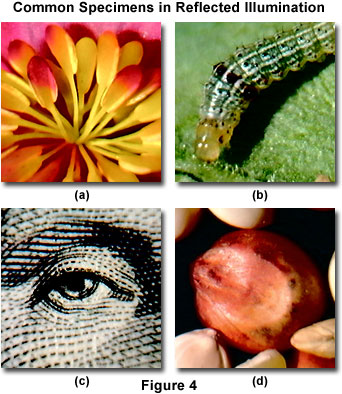
A wide variety of specimens are suitable candidates for imaging in reflected light illumination with the MIC-D digital microscope. Presented in Figure 4 are several examples of common specimens that produce excellent reflected light images. The flowering plant illustrated in Figure 4(a) is a begonia, which displays a dazzling array of bright colors ranging from yellows to reddish hues. Smaller insects are also prime candidates for imaging with the MIC-D microscope. A fall armyworm, caught in its natural environment feeding on a leaf, is the subject of the image displayed in Figure 4(b). This digital image is similar to those produced by macro lenses with traditional photography coupled to complex lighting schemes, but is easily captured on the MIC-D microscopy simply by inverting the leaf with the attached worm and illuminating with reflected light.
A close-up view of George Washington's eye, engraved on a United States Dollar bill, is presented in Figure 4(c). The microscope reveals tiny printing details that are difficult to visualize under a magnifying glass or through a loupe. Finally, an image of the numerous grain and other nutritious components in commercial bird feed are illustrated in Figure 4(d). The high color saturation and contrast displayed by the images presented in Figure 4 are the result of antireflection coatings applied to the stage glass, as well as the excellent color quality of digital images produced by the CMOS image sensor housed in the base of the MIC-D microscope.
In addition to being useful for microscopic imaging of common household and garden specimens, the Olympus MIC-D digital microscope is capable of performing well in an industrial setting where technical image information must be accurate, comprehensive, and reproducible. Typical examples of specimens that are of interest to manufacturers and research scientists are presented in Figure 5. Small mechanical parts, such as the watch gears illustrated in Figure 5(a), are often examined by digital imaging techniques during manufacture and assembly. Machining and casting errors become readily apparent when these miniature components are imaged at high magnification with the MIC-D microscope.
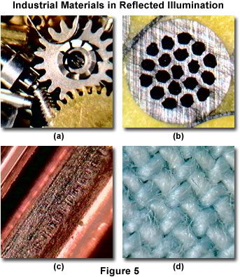
Materials scientists often employ optical metallographic techniques to examine specialized metals, composites, alloys, and synthetic polymers at high magnification. Illustrated in Figure 5(b) is a superconducting wire specimen consisting of a niobium-tin alloy housed in a copper matrix and embedded in a composite-polymer specimen holder. After casting the polymer mixture, the wire specimen is sectioned with a diamond saw, and then sanded and polished for examination under the microscope. Sanding scratches, evident in the copper surface of the wire (see Figure 5(b)), indicate a lack of sufficient polishing in this specimen. The niobium-tin alloy sub-domains appear in an orderly hexagonal array of dark (non-reflecting and also hexagonal) regions when the surface of the superconducting wire is examined. The yellow background is the composite-polymer casting into which the wire is embedded for cutting and processing.
In Figure 5(c), a high-magnification digital image of abrasions on the surface of a copper wire reveals damage that occurred when the wire, part of a wiring harness, was damaged by vibrations in an automobile firewall. The net effect of this damage was to short the electrical circuit in which the copper wire was participating. This type of microscopic analysis is critical to forensic scientists as well as manufacturers and quality control engineers. Another field that is of common interest to police, forensic specialists, and manufacturers is fiber analysis under the microscope. The digital image presented in Figure 5(c) reveals a magnified portion of denim cotton, a material that is widely utilized to fabricate a number of garments. The MIC-D microscope is useful as a tool to reveal patterns in the weave and to analyze individual fibers.
Because of the unique design, the MIC-D digital microscope can perform in a manner similar to research-level inverted metallographic microscopes. On the inverted microscope stand, the specimen is placed on the stage with its surface facing downward. The objective is mounted on a nosepiece, with its front lens facing upward, located beneath the stage in a manner similar to the MIC-D design. Focusing is accomplished on some instruments by having the focusing knobs move the entire nosepiece up or down toward the specimen, but on other inverted microscopes, the nosepiece is in a fixed position and the focusing knobs move the stage closer or further from the objective. The single objective in the MIC-D microscope is designed to move the top lens element, while the lower lens remains fixed for focusing operations.
The advantage of an inverted microscope is that only one side of the mounted specimen under inspection need be perfectly flat, the side facing the objective. This is in contrast to the situation on an upright stand, where a leveling stage may be necessary or the lower side of the specimen mount pressed into a moldable polymer to ensure its horizontality. Another advantage is having the stage unobstructed so that relatively thick or heavy objects can be viewed since the illumination through the objective is positioned beneath the stage. In the case of very large and heavy specimens, the MIC-D microscope can be inverted and the stage placed on top of the specimen for inspection. This feature is useful when the microscope is employed in remote locations to image immobile specimens.
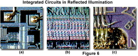
The investigation of integrated circuit surfaces for defects and other properties is of paramount importance to the semiconductor industry. Reflected light microscopy plays an important role in this analysis and most integrated circuit fabrication plants have numerous instruments for inspection and assembly operations. The MIC-D digital microscope is capable of producing medium-range magnification images of packaged and unpackaged integrated circuits and wafers, but does not have the level of magnification necessary to examine the smallest features on very large-scale integrated circuits.
Typical reflected light digital images, captured with the MIC-D microscope, of several integrated circuits are illustrated in Figure 6. The microscope can be utilized to inspect the integrity of bonding wires (Figure 6(a)), and their location within respective pads on the surface of an integrated circuit. In addition, many of the internal circuit details can be examined with the MIC-D microscope (Figure 6(b)). Finally, the results of final package assembly techniques can also be explored in reflected light with the microscope. Note the displaced and unconnected wire present in the digital image in Figure 6(c). The 45-degree oblique illumination angle utilized by the MIC-D in reflected light mode dramatically enhances contrast when imaging integrated circuits. All of the images in Figures 4-6 were captured without assistance from auxiliary illumination sources, and relied solely on light provided from the MIC-D illuminator through the lower microscope port.
In reflected light microscopy analysis, the investigator often must measure details of the specimen being observed. In a traditional microscope, the simplest form of measurement is accomplished with an eyepiece containing a metric scale (inch fractions are also available) and a stage micrometer that is usually a one-millimeter scale divided into a hundred equal divisions, each division thus spanning ten microns. The eyepiece micrometer scale, placed at the eyepiece diaphragm plane or another conjugate plane, is calibrated with the stage micrometer for each objective so that its scale value is known for each objective magnification. Thereafter, only the eyepiece scale is necessary for measurement. In the MIC-D microscope, the interface software contains a micrometer scale bar superimposed on the image in the Live Image screen. The size of the scale bar changes with the zoom magnification of the microscope to enable measurements of feature size directly on the screen. In addition, captured and saved images can include the scale bar for measurements to be performed at a later date on a remote computer.
The oblique illumination angle employed by the MIC-D digital microscope in reflected light mode affords a shadow-cast effect that enhances overall specimen appearance and increases contrast. The results of this lighting configuration are evident in many of the digital images presented in Figures 4 through 6. Because of the unique reflected light configuration utilized for the MIC-D microscope (illumination through a lower optical port), it is difficult to add auxiliary illumination sources without removing the primary source (the illuminator head) from the pathway. However, in situations where additional light is needed, a fiber optic cable can be inserted into the reflected light illumination port to produce more intense illumination.
Contributing Authors
Thomas J. Fellers and Michael W. Davidson - National High Magnetic Field Laboratory, 1800 East Paul Dirac Dr., The Florida State University, Tallahassee, Florida, 32310.
BACK TO MIC-D MICROSCOPE ANATOMY
BACK TO THE OLYMPUS MIC-D DIGITAL MICROSCOPE
Questions or comments? Send us an email.
© 1995-2025 by Michael W. Davidson and The Florida State University. All Rights Reserved. No images, graphics, software, scripts, or applets may be reproduced or used in any manner without permission from the copyright holders. Use of this website means you agree to all of the Legal Terms and Conditions set forth by the owners.
This website is maintained by our
Graphics & Web Programming Team
in collaboration with Optical Microscopy at the
National High Magnetic Field Laboratory.
Last Modification Tuesday, Sep 11, 2018 at 04:00 PM
Access Count Since September 17, 2002: 19146
Visit the website of our partner in introductory microscopy education:
|
|