Polarized Light Microscopy
Polymers in Polarized Light
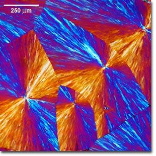
During the solidification of polymer melts there may be some organization of the polymer chains, a process that is often dependent upon the annealing conditions. When nucleation occurs the synthetic polymer chains often arrange themselves tangentially and the solidified regions grow radially.

Polyethyleneglycol (above) in reflected polarized
light with a first-order retardation plate
inserted between the specimen and analyzer.

Polycarbonate (above) in reflected polarized
light with a first-order retardation plate
inserted between the specimen and analyzer.

Liquid crystalline DNA (above) in polarized
light with a first-order retardation plate
inserted between the specimen and analyzer.
These can be seen in crossed polarized illumination as white regions with the black extinction crosses. When these spherulites impinge, their boundaries become polygonal. This can be clearly seen in crossed polars but not under plane-polarized light.
The addition of the whole wave plate (upper photomicrograph) confirms the tangential arrangement of the polymer chains. The banding occuring in these spherulites indicates slow cooling of the melt allowing the polymer chains to grow out in spirals. This information on thermal history is almost impossible to collect by any other technique. Nucleation in polymer melts can take place as the result of accidental contamination or contact with a nucleating surface and can lead to substantial weakening of the product. Identification of nucleation can be a valuable aid for quality control.
Other polymers may not be birefringent (evidenced by the polycarbonate specimen illustrated in center photomicrograph), and do not display substantial secondary or tertiary structure. In other cases, both biological and synthetic polymers can undergo a series of lyotropic or thermotropic liquid crystalline phase transitions, which can often be observed and recorded in a polarized light microscope. The lower image illustrates a birefringent columnar-hexatic liquid crystalline phase exhibited by DNA at very high concentrations (exceeding 300 milligrams/millilter).
Polymer specimens were sandwiched between a microscope slide and cover glass, then observed and photographed using a Nikon Eclipse E600 microscope equipped with crossed polarizers and an intermediate tube containing an insertable retardation plate. The scale bar represents 250 microns.
Contributing Authors
Phillip C. Robinson - Department of Ceramic Technology, Staffordshire Polytechnic, College Road, Stoke-on-Trent, ST4 2DE United Kingdom.
Michael W. Davidson - National High Magnetic Field Laboratory, 1800 East Paul Dirac Dr., The Florida State University, Tallahassee, Florida, 32310.
BACK TO POLARIZED LIGHT INTRODUCTION
