
Polarized Light Microscopy
Microscope Alignment
In polarized light microscopy, proper alignment of the various optical and mechanical components is a critical step that must be conducted prior to undertaking quantitative analysis between crossed polarizers alone, or in combination with retardation plates and compensators. Several essential components must be correctly positioned with respect to both the microscope optical axis and to other mechanical and optical components. The series of alignment steps outlined below are intended for general use with polarized light microscopes and should be applicable to both student and research-level instruments.
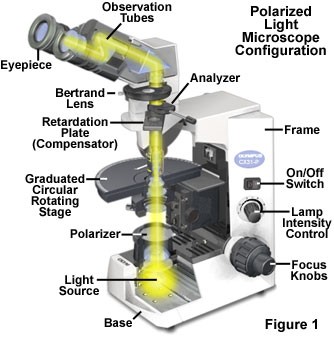
The basic optical and mechanical components of a polarized light microscope are illustrated in Figure 1. At a minimum, these microscopes must be equipped with two linear polarizing elements. One of the polarizers (termed the Polarizer in Figure 1) is placed beneath the stage inside or below the condenser, or covering the microscope light source exit port in the base. The second polarizer (termed the Analyzer in Figure 1) is installed above the objective rear aperture, either in a nosepiece slot or within an intermediate tube positioned between the frame and the observation tubes. Many polarized light microscopes are equipped with a graduated circular stage that can rotate through 360 degrees for quickly changing specimen orientation with respect to the polarizer and analyzer transmission axes. In addition, one of the eyepieces in a polarized light microscope should have a crosshair reticule to identify the center and axes of the optical field. Advanced microscopes include a Bertrand lens for conoscopic observation of interference patterns focused in the objective rear aperture, but this accessory is not absolutely necessary for routine observations. Finally, polarized light microscopes should have an accessory slot in the nosepiece or intermediate tube into which a retardation plate or compensator can be inserted for quantitative analysis of birefringent specimens.
Polarized Microscope Alignment Procedure
The first step in polarized light microscope alignment is to establish proper Köhler illumination with both the polarizer and analyzer removed from the optical pathway. Place a brightfield (stained) specimen on the stage and rotate the 10x objective into the observation position. Focus the specimen with the objective and close the field diaphragm iris to its smallest setting. Bring the partially closed field diaphragm into sharp focus in the same plane as the specimen by adjusting the condenser height. Use the condenser centering screws to translate the image of the field diaphragm iris opening to the center of the eyepiece crosshairs, and then open the diaphragm until the leaves are just outside the viewfield.
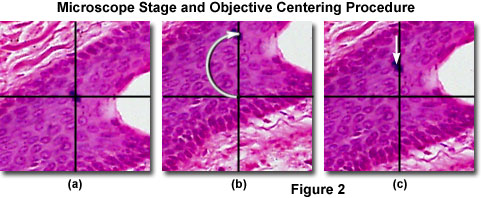
Before inserting the polarizer and analyzer, the 360-degree circular rotating stage should be centered to the 10x objective so specimens will remain in the exact center of the viewfield when they are being rotated. Centering of the stage and objectives is also an important step for quantitative analysis of birefringence and optical path differences. A majority of the circular microscope stages pivot on three adjustable pins, one at the front of the stage for correct positioning and the other two equally spaced at 120-degree angles near the rear of the stage. The stage can be centered with minute adjustments to the rear pivot pins by turning the centering screws. Start by locating a small circular feature on a relatively simple brightfield specimen in an area devoid of other distracting structures. Next, relocate the chosen feature to the center of the viewfield in the eyepiece crosshairs (see Figure 2(a)). Rotate the stage through 180 degrees until the centered specimen feature is overlapped by one of the vertical eyepiece crosshairs (Figure 2(b)). Using the pivot screws, relocate the specimen feature to a distance approximately half way back to the crosshair center (Figure 2(c)). Finally, move the specimen feature back to the center of the crosshairs (Figure 2(a)) and repeat the alignment sequence. After a few cycles, the specimen feature should be centered in the viewfield as the stage is rotated.
After the stage has been centered with respect to the microscope optical axis with the 10x objective installed in the optical train, the other objectives (4x, 20x, 40x, and 100x) should be sequentially centered to the stage. Microscopes having centerable objectives contain a pair of Allen (or a similar drive) setscrews in the nosepiece that translate the objective laterally within its seat. Each objective can be centered using the procedure described above for the circular stage by using the objective centering tools provided by the manufacturer. Accurate centering of the stage and all objectives is paramount to quantitative analysis in polarized light, and avoids the operator losing sight of specific features in the viewfield during stage rotation. After completing the centering procedure, review the steps to ensure all of the objectives on the microscope are accurately centered before continuing.
Establishing Köhler illumination and centering the microscope stage and objectives is easily accomplished in brightfield mode (but can also be undertaken with a birefringent specimen in polarized light mode, if necessary). To continue with alignment of the polarizing components, install the fixed or rotating polarizing element in the condenser or a housing on the light source exit port in the microscope base. Many polarized light microscopes are equipped with a fixed polarizer that has a transmission vibration axis oriented East-West, or left-to-right when standing in front of the microscope. Other microscopes have polarizers that can be rotated through 180 or 360 degrees, and are often mounted into frames with graduated increments ranging from 1 to 90 degrees. Ensure that the polarizer is correctly secured into position and either permanently fixed into its holder or placed in the zero position. The polarizer transmission vibration axis must be set to the East-West orientation in this step.
Insert the analyzer into the microscope nosepiece or intermediate tube. Virtually all research-level polarized light microscopes have a rotating analyzer mounted in a rectangular frame that enables rotation of the element through 180 or 360 degrees. Student microscopes often have a fixed analyzer (as well as a fixed polarizer) to ease the burden of crossed polarizer alignment. Rotate the analyzer while examining a birefringent specimen on the stage with the 10x objective. When the transmission axes of the analyzer and polarizer are crossed at a 90-degree angle, maximum specimen birefringence (equivalent to maximum specimen brightness) should be observed on a very dark background (a condition that is termed maximum extinction). Under crossed polarized illumination, the vibration axis of the analyzer should be oriented North-South or front-to-back while standing in front of the microscope. A critical assessment for maximum extinction can only be accomplished while observing the background intensity through the microscope eyepieces. Keep in mind that at this point, maximum extinction only indicates that the polarizers are crossed, but does not guarantee that their transmission axes are perfectly oriented East-West and North-South. The latter aspect is addressed in the next step.
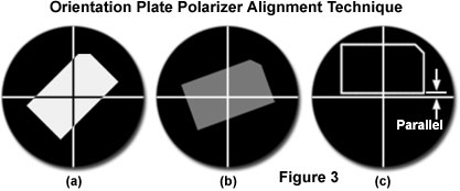
Calibration of the polarizer and analyzer axis alignment can be accomplished by one of two methods. Many manufacturers provide a polarized light microscope orientation plate with their research-level microscopes to assist in alignment of the crossed polarizers. These plates contain a perfectly cut rectangular thin birefringent crystal having an optical axis that is parallel to the long edge of the crystal (see Figure 3). The crystal is mounted flat on a microscope slide and designed specifically for use on circular polarized light microscope stages. When the long axis crystal is oriented at a 45-degree angle to the polarizer and analyzer transmission azimuths (Figure 3(a)), maximum birefringence is observed in polarized light. Rotating the crystal towards the polarizer axis progressively reduces the level of birefringence (Figure 3(b)) until it is eliminated when the long axis is exactly parallel to the polarizer transmission azimuth (and the horizontal eyepiece crosshair; see Figure 3(c)).
At this point, the crystal birefringence is completely extinguished and should be indistinguishable from the background. Note that the outline of the crystal is artificial in Figure 3(c), and is included only to demonstrate that the long axis is parallel to the polarizer azimuth. If the polarizer and analyzer are not positioned exactly in a East-West and North-South orientation (respectively), then the long axis of the crystal will not be parallel to the eyepiece crosshairs when the birefringence is completely extinguished. In this case, rotate the long axis of the crystal until it is parallel to the horizontal microscope crosshair, and then rotate the polarizer until minimum birefringence is observed in the eyepieces. Next, rotate the analyzer until the crystal birefringence is completely extinguished.
If a Bertrand lens or focusing telescope is available with the polarized light microscope, alignment of the polarizer and analyzer transmission azimuths can be performed using one of these optical components. Without a specimen on the stage, cross the polarizers and insert the eyepiece telescope into the observation tubes or swing the Bertrand lens into the optical pathway. Focus the telescope or Bertrand lens on the objective rear aperture. A dark polarization cross can be observed at maximum extinction (Figure 4(a)) with brighter regions flanking the arms of the cross, which should be oriented vertically and horizontally. In most cases, the horizontal and vertical components of the polarization cross are wider in the center of the field and narrower at the periphery.
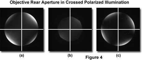
The polarization cross geometry originates from the depolarizing effects of spherical lens surfaces in the condenser and objective, and may vary in size and shape depending upon the quality (strain reduction or elimination) of the lens systems. However, the presence of a polarization cross is normal in most microscopes and can not generally be considered an artifact. The cross should be centered in the viewfield (when superimposed on the eyepiece crosshairs) and appear perfectly aligned in a North-South and East-West direction. If this is not the case (as illustrated in Figure 4(c)), the polarizer and analyzer should be rotated in combination until the proper orientation is achieved. As discussed above, perfect alignment of the polarization cross (thus, the polarizers) with a transmission axis at zero degrees is essential for performing quantitative measurements of birefringence azimuthal angles with or without a retardation plate or compensator in the optical pathway. The polarization cross reference calibration is also useful if a fixed polarizer or analyzer becomes misaligned in the mount.
The final step in polarized light microscope alignment is to adjust the condenser aperture diaphragm so the bright outer regions of the polarization cross that are visible at the edge of the objective aperture are blocked. Figure 4(b) illustrates a properly adjusted condenser diaphragm. This step dramatically improves the extinction factor of the microscope optical system, and the field will appear maximally dark when viewed in orthoscopic mode (without a Bertrand lens or focusing telescope). After the microscope has been aligned and the polarization axes calibrated, it is ready for quantitative analysis of birefringent specimens.
Contributing Authors
Peter Dimitruk - Scientific Equipment Group, Olympus America Inc., Two Corporate Center Drive, Melville, New York, 11747.
Michael W. Davidson - National High Magnetic Field Laboratory, 1800 East Paul Dirac Dr., The Florida State University, Tallahassee, Florida, 32310.
BACK TO POLARIZED LIGHT MICROSCOPY