
Fluorescence Microscopy
Light Sources
In most fluorescence microscopy applications, the number of photons reaching the eye or other detector, such as a video camera, CCD digital camera system, or photomultiplier, is usually very low. This is because the quantum yield of most fluorochromes is low (quantum yield is the ratio of the number of quanta emitted by the specimen as compared to the number of quanta absorbed). In order to generate enough excitation light intensity to furnish a level of emission capable of detection, powerful light sources are needed, usually arc (burner) lamps similar to the example that is presented in Figure 1. These lamps are filled with high pressure gases and should be handled with caution.
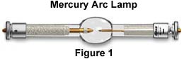
The most common lamps are the mercury burners, ranging in wattage from 50 watts to 200 watts and the xenon burners ranging from 75 watts to 150 watts. The mercury burner lamp in Figure 1 consists of two electrodes sealed under high pressure in a quartz glass envelope which also contains mercury.
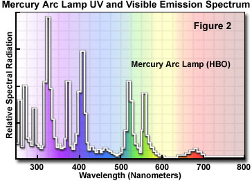
These light sources are usually powered by a D.C. power supply furnishing enough start-up power to ignite the burner (by ionization of the gaseous vapor) and to keep it burning with a minimum of flicker. The power supply should have a timer to enable you to keep track of the number of hours the burner has been in use. Arc lamps lose efficiency and are more likely to shatter, if used beyond their rated lifetime. The mercury burners do not provide even intensity across the spectrum from ultraviolet to infrared (See Figure 2 for the emission spectrum of the mercury burner). Much of the intensity of the mercury burner is expended in the near ultraviolet, with peaks of intensity at 313, 334, 365, 406, 435, 546, and 578 nanometers. At other wavelengths of visible light, the intensity is steady but not nearly so bright, but still usable for blue excitation. It also should be understood that mere wattage is not the only consideration for determining brightness.
Fluorescence Lamp Specifications
|
|
|||||||||||||||||||||||||||||||||||||||||||||||||
|
|
|
Table 1
Another important criterion is the size of the arc; the brightness per unit area of the arc encompassed within the back aperture of the objective is a better measure of the useful brightness of the burner. Using the criterion, you will note that of the three mercury burners listed in Table 1, the 100 watt burner (other things being equal) is the brightest of the three. Also important in your selection of a burner is whether or not the spectral intensity peaks of the burner's wavelengths match the excitation requirements for the fluorochromes staining the specimen. Whenever an illumination system is being evaluated, it is necessary to consider the entire system including collector lenses and the use of aperture and field diaphragms in securing K�hler illumination.
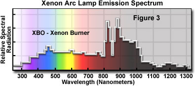
The xenon burners have much more even intensity across the visible spectrum than do the mercury burners (See Figure 3); they do not have the very high spectral intensity peaks that are characteristic of mercury burners. Xenon lamps are deficient in the ultraviolet; they expend a large proportion of their intensity in the intra-red, and therefore the use of such lamps requires care in control of heat. Short-gap xenon burners are usually more desirable because the size of the arc is such that its light may be more readily included within the back aperture of the objective, thus avoiding waste of light intensity.
|
|
|||||||
|
|
|
|||||||
Always adhere to the safety procedures listed above when installing or changing mercury or xenon arc lamps.
Mercury burners have a life of 200 hours; xenon burners several hundreds of hours. Frequent on-off switching reduces lamp life. When the burners reach their rated lifetime, the spectral emissions may change and the quartz envelope weakens.
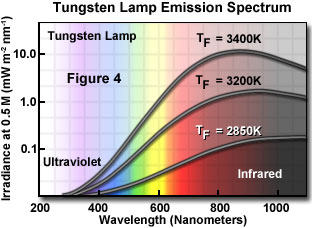
Sometimes, tungsten-halogen bulbs are used, especially for blue or green excitation with brightly emitting specimens. Their output is relatively even across the visible spectrum (Figure 4); they are deficient in the near-ultraviolet and also have a relatively high proportion of intensity in the infrared. These lamps do not require expensive power supplies for ignition but are powered by low voltage transformers; the bulbs last for thirty to fifty hours when used at their maximum rated voltage.
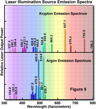
In recent years, there has been increasing use of lasers in optical microscopy, particularly the argon-ion laser with powerful emission capability at 488 and 514 nanometers. Laser sources, despite the high cost, have become especially useful in laser scanning confocal microscopy. There are a number of different types of lasers that each provide a unique emission spectrum. Figure 5 illustrates the emission spectra of the two most commonly used lasers in fluorescence microscopy.
This technique, with its many variations of equipment, has proved to be a powerful tool in rendering very sharp fluorescence images by ingeniously controlling out-of-focus light. This is accomplished through scanning and imaging extremely small, shallow areas successively. The optical sections of the specimen are stored in a computer and reconstituted into the whole image which can then be displayed on a video monitor or printed with a video printer.
| Interactive Tutorial |
|
||||||||||
|
|||||||||||
Lamp Alignment - Microscope companies may offer an optional centering screen to facilitate the centering of the image of the lamp arc to the back aperture of the objective. This accessory has, at its upper end, the standard Royal Microscopical Society (RMS) thread and can be screwed into the nosepiece. It is placed there and rotated into the light path. The lower face of the accessory has a frosted, orange-colored glass with an inscribed crosshair.
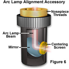
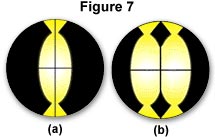
Light coming down from the dichroic mirror strikes the built-in reflector of the centering screen and is reflected onto the crosshairs, as illustrated in Figure 6. As you manipulate the lamp condenser knob and the centering screws on the lamp socket, you can move the image so that it is centered to the crosshairs (Figure 7(a)). The size of the image of the arc can be made bigger or smaller by manipulating the lamp condenser lever. When you are done with the centering accessory, it can be replaced by a regular objective. If the lamphouse contains a mirror, the mirror position should be adjusted so that the arc image in the mirror is positioned parallel and adjacent to the arc image itself as shown in Figure 7(b).
If you do not have a centering screen, the following alternative procedure can be used. Focus the specimen with the 10x objective. Then rotate the nosepiece so that an empty opening on the nosepiece is in the optical path of the microscope. Place a white card on the stage (in place of the specimen) and you will see the image of the arc projected onto the card. By manipulating the lamp condenser knob and the burner centering screws on the lamphouse, you can center the image of the arc to the optical axis of the microscope.
Contributing Authors
Mortimer Abramowitz - Olympus America, Inc., Two Corporate Center Drive., Melville, New York, 11747.
Michael W. Davidson - National High Magnetic Field Laboratory, 1800 East Paul Dirac Dr., The Florida State University, Tallahassee, Florida, 32310.
BACK TO FLUORESCENCE MICROSCOPY