
Diffraction of Light
In his 1704 treatise on the theory of optical phenomena (Opticks), Sir Isaac Newton wrote that "light is never known to follow crooked passages nor to bend into the shadow". He explained this observation by describing how particles of light always travel in straight lines, and how objects positioned within the path of light particles would cast a shadow because the particles could not spread out behind the object.
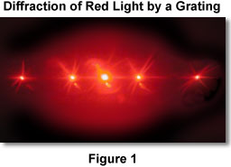
On a large scale, this hypothesis is supported by the seemingly sharp edges of shadows cast by rays from the sun. However, on a much smaller scale, when light waves pass near a barrier, they tend to bend around that barrier and spread at oblique angles. This phenomenon is known as diffraction of the light, and occurs when a light wave passes very close to the edge of an object or through a tiny opening, such as a slit or aperture. The light that passes through the opening is partially redirected due to an interaction with the edges. An example of light diffraction is presented in Figure 1 for coherent red laser light passing through a very tiny line grating composed of a series of bars on a glass microscope slide. The bars diffract the laser light into widely spaced periodic beams of bright light that can be observed in the figure. Diffraction is a phenomenon similar to dispersion, but is not related to a variation in the wavelength of light.
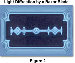
Bright bands that are often seen inside the edges of geometric shadows are the result of diffraction. When light waves originating from a distant point of light strike an opaque object, they tend to bend around the edges, curving both into the shadow and back through the path of other light waves from the same source. The waves that bend around behind the object create a bright line where the shadow would ordinarily begin, but waves that bounce back into the path of the light overlap waves from the source, creating an interference pattern of light and dark bands around the edge of the object (see Figure 2). Diffraction is often explained in terms of the Huygens principle, which states that each point on a wavefront can be considered as a source of a new wave.
Depending on the circumstances that give rise to the phenomenon, diffraction can be perceived in a variety of different ways. Scientists have cleverly utilized diffraction of neutrons and X-rays to elucidate the arrangement of atoms in small ionic crystals, molecules, and even such large macromolecular assemblies as proteins and nucleic acids. Electron diffraction is often employed to examine periodic features of viruses, membranes, and other biological organisms, as well as synthetic and naturally occurring materials. No lens exists that will focus neutrons and X-rays into an image, so investigators must reconstruct images of molecules and proteins from the diffraction patterns using sophisticated mathematical analysis. Fortunately, magnetic lenses can focus diffracted electrons in the electron microscope, and glass lenses are very useful for focusing diffracted light to form an optical image that can easily be viewed.
A very simple demonstration of light diffraction can be conducted by holding one hand in front of a strong light source and slowly bringing two fingers close together while observing the light transmitted between them. As the fingers approach one another and come very close together (almost touching), one can begin to see a series of dark lines parallel to the fingers. The parallel dark lines together with the bright areas between them are actually diffraction patterns. This effect is clearly demonstrated in Figure 2, for diffraction rings that appear surrounding the sharp edges of a razor blade when it is illuminated with intense blue light from a laser source.
Another simple, but very common, example of diffraction occurs when light is scattered or bent by small particles having physical dimensions in the same order of magnitude as the wavelength of light. A good illustration is the spreading of automobile headlight beams by fog or fine dust particles. The amount of scattering and the angles taken by the redirected light beams are dependent upon the size and density of the particles causing the diffraction. Light scattering, a form of diffraction, also underlies the blue color of the sky and the often beautifully colored sunrises and sunsets that can be observed on the horizon. If the Earth were devoid of an atmosphere (lacking air, water, dust, and debris), the sky would appear black, even during the daytime. When light from the sun passes through the Earth's atmosphere, localized volumes of gas molecules having varying densities, due to temperature fluctuations and the amount of water vapor present, will scatter the light. The shortest wavelengths (violet and blue) are scattered to the greatest extent, rendering the sky a rich, deep blue color. When there is a considerable amount of dust or moisture in the air, longer (primarily red) wavelengths also become scattered along with the blue wavelengths, causing the blue sky to become whiter in color.
When the sun is high (around noon) in a clear dry atmosphere, most of the visible light passing through the atmosphere is not scattered to a significant degree, and the sun appears almost white on a deep blue background. As the sun begins to set, the light waves must pass through increasing amounts of atmosphere, usually containing larger quantities of suspended dust and moisture. Under these circumstances, longer wavelengths of light become scattered and other colors start to dominate the color of the sun, which ranges from yellow to orange, finally turning red just before it drops below the horizon.
We can often observe pastel shades of blue, pink, purple, and green in clouds, which are generated by a combination of effects when light is refracted and diffracted from water droplets in the clouds. The amount of diffraction depends on the wavelength of light, with shorter wavelengths being diffracted at a greater angle than longer ones (in effect, blue and violet light are diffracted at a larger angle than is red light). The terms diffraction and scattering are often used interchangeably and are considered to be almost synonymous in many cases. Diffraction describes a specialized case of light scattering in which an object with regularly repeating features (such as a periodic object or a diffraction grating) produces an orderly diffraction pattern. In the real world, most objects are very complex in shape and should be considered to be composed of many individual diffraction features that can collectively produce a random scattering of light.
| Interactive Java Tutorial | |||||||||||
|
|||||||||||
In the microscope, scattering or diffraction of light can occur at the specimen plane due to interaction of the light with small particles or features, and again at the margins of the objective front lens or at the edges of a circular aperture within or near the rear of the objective. It is this diffraction, or spreading of light, that makes it possible to observe magnified images of specimens in the microscope, however it is also diffraction that limits the size of objects that can be resolved. If light passes through a specimen and is not absorbed or diffracted, the specimen will not be visible when viewed through the eyepieces. The manner in which an image is formed in the microscope depends on the diffraction of light into divergent waves, followed by their subsequent recombination into a magnified image through constructive and destructive interference.
When we view a specimen, whether directly or with a microscope, telescope, or other optical instrument, the image we see is composed of a myriad of overlapping points of light emanating from the plane of the specimen. Therefore, the appearance and integrity of the image from a single point of light holds a significant amount of importance with regards to formation of the overall image. Because the image-forming light rays are diffracted, a single point of light is never really seen as a point in the microscope, but rather as a diffraction pattern containing a central disk or spot of light having a finite diameter and encircled by a fading series of rings. As a result, the image of a specimen is never an exact representation of the specimen, and a lower limit is imposed on the smallest detail in the specimen that can be resolved. The resolving power is the ability of an optical instrument to produce clearly separated images of two adjacent points. Up to the point at which diffraction causes the resolution to be limited, the quality of the lenses and mirrors in the instrument, as well as the properties of the surrounding medium (usually air), determine the final resolution.
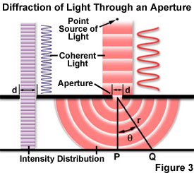
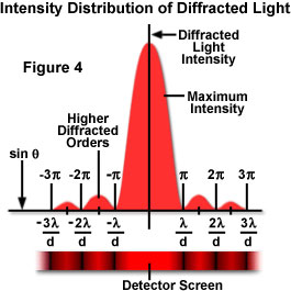
Several of the classical and most fundamental experiments that help explain diffraction of light were first conducted between the late seventeenth and early nineteenth centuries by Italian scientist Francesco Grimaldi, French scientist Augustin Fresnel, English physicist Thomas Young, and several other investigators. These experiments involve propagation of light waves though a very small slit (aperture), and demonstrate that when light passes through the slit, the physical size of the slit determines how the slit interacts with the light. If the wavelength of light is much smaller than the aperture or slit width, a light wave simply travels onward in a straight line after passing through, as it would if no aperture were present (as presented in Figure 3). However, when the wavelength exceeds the size of the slit, diffraction of the light occurs, causing the formation of a diffraction pattern consisting of a bright central portion (the primary maximum), bounded on either side by a series of secondary maxima separated by dark regions (minima; see Figure 4). The maxima and minima are created by interference of diffracted light waves. Each successive bright band becomes less intense proceeding outward, away from the central maximum. The width of the central bright portion, and the spacing of the accompanying sidebands, depends on the size of the aperture (slit) and the wavelength of the light. This relationship can be described mathematically and demonstrates that the width of the central maximum decreases with decreasing wavelength and increasing aperture width, but can never be reduced to the size of a point light source.
The intensity distribution of light diffracted by the single slit experiment is presented in Figures 3 and 4. It is assumed that both light beams in Figure 3 are composed of coherent, monochromatic waves emitted from a point source that is far enough away from the slit for the wavefronts to be considered linear and parallel. Light passing through aperture d on the right-hand side of the figure has a wavelength larger than the aperture and is diffracted, with the primary incident light beam landing at point P and the first secondary maximum occurring at point Q. As shown on the left-hand side of Figure 3, when the wavelength is much smaller than the aperture width (d), the wave simply travels through in a straight line, just as it would if it were a particle or no aperture were present. However, when the wavelength exceeds the size of the aperture, it is diffracted to produce a central peak containing most of the light intensity accompanied by secondary higher-order maxima and intensity minima governed according to the equation:
where q is the angle between the central incident propagation direction and the first minimum of the diffraction pattern, and m indicates the sequential number of the higher-order maxima. The light intensity is maximum at q = zero degrees, and decreases to a minimum (where the intensity is zero) at angles dictated by the equation above. The experiment produces a bright central maximum, which is bounded on both sides by secondary maxima, with the intensity of each succeeding secondary maximum decreasing as the distance from the center increases. Figure 4 illustrates this principle with a plot of beam intensity versus diffraction radius. Note that the minima occurring between secondary maxima are positioned in multiples of pi (p).
Both the experiment described above, and the demonstration of diffraction using light passing between the fingers, utilize a narrow slit as an aperture to produce a diffraction pattern. All optical instruments, including microscopes, utilize circular lenses and apertures, as does the human eye itself. Circular apertures produce similar diffraction phenomena, although with circular symmetry (instead of linear geometry, as in the case of slits). Therefore the diffraction pattern of a point source of light, if highly magnified, is seen to consist of a central bright disk surrounded by a series of diffraction rings (the secondary maxima and minima). When a lens, such as a microscope objective lens, is properly focused, the light intensity at the minima between the bright rings in the pattern is zero. No matter how perfect the lens is, the secondary diffraction maxima cannot be eliminated nor can the central spot be reduced to a single point of light (unless the lens could be made with an infinite diameter).
| Interactive Java Tutorial | |||||||||||
|
|||||||||||
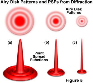
The central diffraction spot or disk is called an Airy disk, named after Sir George Airy, who described many aspects of the concept in the nineteenth century. The Airy disk pattern (illustrated in Figure 5) is a direct result of diffraction, and demonstrates the alteration of points of light that make up an image using an optical instrument such as a microscope. In a manner that is similar to diffraction by a slit, the size of the central disk produced by circular lenses is related to the wavelength of the light and the diameter or aperture angle of the lens. In the case of a camera or telescope lens receiving light from an object at great (infinite) distance, the aperture angle depends on the focal ratio f/D, where D is the lens diameter and f is the focal length. The focal ratio is usually referred to in photography as the f-number of the lens. The aperture angle can be considered to be the angular diameter of the lens, measured from a reference point at the lens aperture to a point in the image plane positioned at the focal length (f) away from the lens. The radius of the diffraction disk (d) is given by the relationship:
With objective lenses employed by the microscope, the concept of numerical aperture (NA) is used instead of the angular aperture. The definition of numerical aperture includes the refractive index of the medium positioned between the front of the lens and the microscope specimen slide, and the half angle over which the lens can collect light from a nearby specimen placed at the focal distance. Using the variable n to designate the refractive index, and q for the half angle aperture, the numerical aperture of a microscope objective is defined as:
The radius of the diffraction spot (r) for a point of light in the image plane (see Figure 4) is given by the related expression:
The Airy disk patterns, along with point spread functions, at three hypothetical resolutions are presented in Figure 5. The point spread function is a three-dimensional representation of the diffraction pattern occurring along the optical axis of the microscope. As the lateral resolution increases, Airy disk size decreases and the corresponding point spread function narrows. This can be demonstrated while observing the figure by comparing the Airy disk and point spread function in (a), which display the lowest resolution, with the corresponding set in (c) that have the highest resolution of the group. Experimentally, resolution can be increased by decreasing the wavelength of light utilized to image the specimen (from white light to blue, for example) or by increasing the numerical aperture of the objective and condenser combination. Under most circumstances, it is easier and far more practical to select an objective having a higher numerical aperture in order to increase the resolution of the images produced by the microscope.
Regardless of whether an image is formed in the microscope or another optical instrument, the size of a diffracted point of light becomes smaller with decreasing wavelength or increasing numerical aperture, but always remains a disk that is larger than the point of light originating from the specimen (or other object) being imaged. In evaluating the resolution that is possible with a microscope, if the size of the individual diffraction spot is the limiting factor (rather than lens aberrations or other variables), the image achieved is said to be diffraction limited. For any optical instrument, therefore, the light gathering ability is fixed by the aperture angle or numerical aperture, and the resolution obtained is controlled by varying these values and the wavelength of light utilized to capture the image in order to obtain the smallest diffraction disk size that is possible with the instrument. Only when specimen details seen in the image are larger than this limiting disk size, can conclusions be made about the size, shape, and arrangement of the features.
Contributing Authors
Thomas J. Fellers and Michael W. Davidson - National High Magnetic Field Laboratory, 1800 East Paul Dirac Dr., The Florida State University, Tallahassee, Florida, 32310.