
Color Temperature
The color temperature model is based on the relationship between the temperature of a theoretical standardized material, known as a black body radiator, and the energy distribution of its emitted light as the radiator is brought from absolute zero to increasingly higher temperatures. As the name implies, black body radiators completely absorb all radiation, without any transmission or reflection, and then re-emit all incident energy in the form of a continuous spectrum of light representing all frequencies in the electromagnetic spectrum. Although the black body radiator does not actually exist, many metals behave in a manner very similar to a theoretical radiator.
Imagine that the black body radiator is heated to the temperature of freezing water, equal to 273 kelvins (or K), zero degrees Celsius, or 32 degrees Fahrenheit. There is no obvious difference in the appearance of the radiator. The black body is then further heated to the temperature of boiling water: 373 kelvins, 100 degrees Celsius, or 212 degrees Fahrenheit. Still, no change in appearance occurs. However, if the black body continues to be heated, it will begin to glow and give off its own light. When the temperature reaches 3200 kelvins, the radiator will be emitting light with a visible light wavelength range equivalent to the color temperature of the spectrum produced by a tungsten filament, typical of those found in microscope lamps. Heating the black body to even higher temperatures will result in the emission of a wide spectrum of colors, the nature of which is temperature-dependent.
The absolute temperature of the black body radiator is expressed in kelvins (usually abbreviated simply as K, omitting the reference to degrees), which is equivalent to degrees Celsius plus 273 degrees. For example, 1,000 kelvins (or K) equals 727 degrees Celsius. Therefore, we can define the color temperature of a light source as the value of the absolute temperature of a black body radiator when the radiator color spectrum, or chromaticity, matches that of the light source. In the case of fluorescent lamps, which can only approximate the chromaticity of a black body, the corrected term correlated color temperature is applied through a calculated chromaticity value.
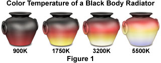
Using a black metal pot as a model for the black body radiator (see Figure 1), color changes are first apparent as the pot begins to glow a dull red when heated to a temperature of about 900 K. As the temperature is increased to a range between 1,500 K and 2,000 K, the pot turns from yellowish to brighter red in color. Still further temperature increases, to a range above 3,000 K, transforms the color to a yellow-white (the color temperature of a tungsten filament), and at 5,000 K and above, a bluish-white color appears at the base of the pot (the color temperature of daylight). Progressive temperature increases of the black body shift a greater proportion of emitted light into the higher frequency regions (shorter wavelengths) of the visible light spectrum.
| Interactive Java Tutorial | |||||||||||
|
|||||||||||
There are two important points to consider when examining color temperature phenomena. The color temperature value of a light source refers only to the visual appearance of the source, but does not necessarily describe the effect this source will have on photographs or digital images. Also, color temperature does not take into consideration the spectral distribution of a visible light source. In cases where a light source, such as a fluorescent lamp, arc-discharge burner, laser, or gas discharge lamp, does not have a spectral distribution similar to that of a black body radiator, its color temperature alone is not a reliable means of selecting suitable filters or creating look-up tables for color balance corrections. Therefore, although two different light sources may be described as having the same color temperature, exposed photographic emulsions or digital images lacking proper white balance baseline adjustments may respond differently to the sources. When using fluorescent lamps or similar light sources, a per-wavelength comparison of sensitivity and spectral output is often necessary to determine the correct filters for color temperature balance.
The concept of color temperature is very important in the traditional photography arena, where film emulsions must be balanced to accurately render color using different light sources. For example, films intended to be used outside in ordinary daylight, fluorescent, and flash lighting are balanced during manufacture for a color temperature of 5500 K while films made for indoor tungsten light bulb use are balanced for a color temperature of 3200 K to 3400 K. The 5,500 K average value of the sun's color spectrum varies during different parts of the day and is also seasonally and latitudinally dependent. In the early morning and late evening, the color temperature will drop to 5,000 K and below, causing color shifts that result in warmer (redder) color renditions, familiar to some photographers as the "golden hours". Although this wide variation in color temperature is not critical for optical microscopy applications, it does point out the fluctuations that must be addressed in general photography and photographic lighting scenarios.
A majority of the light bulbs that are used for indoor illumination have some form of tungsten filament (with the exception of fluorescent bulbs) and emit a wavelength spectrum centered in the 3,200 K color temperature region. Common fluorescent indoor lamps have a color temperature range between 4,000 K and 5,000 K, more closely approximating daylight lighting conditions. Using daylight-balanced films under tungsten illumination will shift all color tones towards a decidedly yellow cast. Likewise, using tungsten-balanced films under daylight illumination will shift color tones towards a bluer cast. All major film manufacturers have one or several 3200 K films available in 35 mm transparency format. Transparency film is preferable to color negative film for several reasons. First, all color negative films are color balanced for 5500 K and must be manipulated during printing to avoid the yellow cast mentioned above. Most photo processors cannot (or will not) produce satisfactory results with photomicrographs on color negative film. Also, the contrast and color saturation in transparency film cannot be equaled by color negative film.
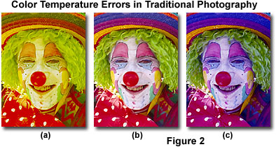
The clown photographs presented in Figure 2 illustrate the proper use of color balance between film emulsions and illumination sources. The clown in the center (Figure 2(b)) was photographed under natural sunlight using daylight-balanced (5500 K) Fujichrome Velvia. Using the same film, the clown on the left (Figure 2(a)) was photographed under tungsten illumination. Note that all hues are shifted to longer wavelengths and the overall image has a definite yellow cast. The clown on the right (Figure 2(c)) was photographed under natural sunlight, but this time the film was tungsten-balanced (3200 K) Fujichrome 64T. Under these conditions, the image has an overall blue cast and appears very unnatural. By carefully coordinating lighting conditions with film emulsion, most photographers can easily take beautiful images that accurately reproduce the actual colors of the subject.
A comprehensive color temperature chart (see Table 1) can be a valuable resource to help illustrate the range of colors generated by inside (artificial) and outside (natural sunlight) light sources. Values falling below 3,500 K are generally considered to be in the tungsten range, and neutral colors viewed under this illumination often appear redder (warmer) than they do under natural daylight. With digital imaging using video tubes and CCD image sensors, color temperature becomes less of a concern because digital techniques eliminate the need for photographic films and their inherent color temperature sensitivities. However, the electronic equipment utilized to capture digital images must contain functions that enable the adjustment of a white balance setting to establish a baseline for color temperature.
Accepted convention for evaluation of light sources, in regards to filter requirements for color balance adjustment, employs the reciprocal of color temperature, which is referred to as microreciprocal degrees (or mireds, when multiplied by a factor of one million). This quantitative approach is useful because a given sum of reciprocal units corresponds approximately to the same color difference for most light sources that emit in the visible spectrum (in the range from 1000 K to 10,000 K). For instance, a color conversion filter that produces a 100 K color temperature decrease in a 3,200 K light source will produce a decrease of about 1,000 K in a 10,000 K light source. Although the color temperature differential between conversion of the 10,000 K and 3,200 K light sources is 1,000 K and 100 K, respectively, the actual filtration difference is virtually the same when compared as mired units (10 versus 11 mireds).
More recently, the term reciprocal megakelvins (1/MK) has been used by Kodak and others to replace mireds. Color temperature quantities expressed in reciprocal megakelvins have the same value as mireds, but the number is determined by first expressing the color temperature in megakelvins (1 MK = 1,000,000 K) and taking the reciprocal.
Color Temperatures of Common Light Sources
|
||||||||||||||||||||||||||||||||||||||||||||||||||||||
Table 1
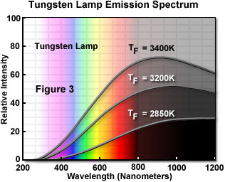
An important question for the microscopist is how to ensure that the color temperature of light reaching the film or image sensor matches the film's color temperature or falls within the range of the digital look-up tables. The color temperature of light emanating from the heated coil of a tungsten-halogen bulb is dependent on the voltage supplied to the bulb in order to heat its filament. Tungsten and tungsten-halogen lamps emit a continuous spectrum of energy that is manifested by a relatively constant output for each wavelength. A majority of the energy emitted by these lamps is in the long wavelength part of the spectrum (red and higher), and they subsequently produce a tremendous amount of heat that is not useful for illumination. In fact, about 90 percent of the energy emitted by tungsten and tungsten-halogen lamps is released in the form of infrared radiation and heat, which does not contribute to illumination in the visible region. The ultraviolet, visible, and infrared spectrum of a typical tungsten lamp is illustrated in Figure 3 for three specific color temperatures. Note that the spectral distributions are similar for each color temperature, with the ratio of blue to red increasing as color temperature is increased by raising the voltage applied to the lamp.
Table 1 catalogs the color temperature of several common microscope bulbs and a variety of other light sources providing either natural or artificial illumination. For tungsten and tungsten-halogen lamps, the greater the voltage setting of the microscope's step-down transformer, the higher the color temperature of the emitted light. As the voltage is raised, the white light becomes more bluish; as the voltage is reduced, the light becomes more reddish-yellow. Once the voltage for color photomicrography or digital imaging has been correctly set, the voltage regulator is no longer used to adjust brightness, because such an adjustment will affect the color temperature of film or the white balance on a digital imaging sensor. High-intensity and ultra high-intensity white light emitting diodes have recently been introduced as light sources for optical microscopy, and have color temperatures ranging from 6,500 K to 9,500 K, rivaling daylight (See Table 1).
The test of properly balanced light, matched to the film's design or a digital camera look-up table, is to have the clear background of a photomicrograph or digital image appear white. A bluish background indicates too high a color temperature, while a yellowish background signifies too low a color temperature (see Figures 2 and 7). To facilitate obtaining the correct setting for photomicrography or digital imaging, many modern microscopes have a photovoltage button that, when pressed, automatically sets the 12 volt 100-watt halogen lamp at 9 volts, or the 6 volt 20-watt halogen lamp at 5 to 6 volts to deliver light approximating 3,200 K. While the most common bulbs (12 volt, 100-watt halogen; or 6 volt 20-watt or 30-watt halogen) can be set to yield a color temperature close to 3,200 K, none of these bulbs (except the xenon and mercury burners) can radiate light suitable for daylight-balanced films. In order to produce light simulating daylight quality, a color conversion filter must be placed in the light path, either on the light port of the microscope or in a built-in holder.
Color Conversion and Balancing Filters
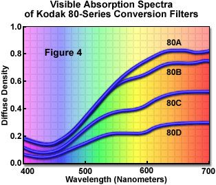
The most common variety of conversion filter (producing large jumps in color temperature) is the Kodak 80A filter (3,200 K to 5,500 K) or the related 80B, 80C, 80D series of filters (see Figure 4). For Olympus microscopes, the equivalent daylight-balanced filter is called the LBD filter, and for Nikon microscopes the filter is termed the NCB filter. Kodak 80-series conversion filters display an absorption maximum centered in the 600-650 region of the visible spectrum, which includes most of the yellow and red wavelengths. The 80A filter has the highest extinction coefficient and thus, by absorbing more red and yellow light, will produce the greatest shift in effective color temperature, followed by the 80B, 80C, and 80D.
For small increases in color temperature, the light blue Kodak 82-series filters can be used. Conversely, for small drops in color temperature, the light yellow Kodak 81-series filters are employed. When attempting to convert the color temperature of a daylight-balanced microscope light source, such as a xenon lamp or flash tube, for use with tungsten-balanced color film, one of the appropriate amber Kodak 85-series filters is inserted. Although it is far more practical to utilize a microscope equipped with a tungsten-halogen light source, especially for critical photomicrography, these filters will serve in cases where it is impossible to use other lamps (such as microscopes equipped with arc-discharge burners or flash tubes).
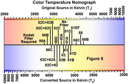
The "fine tuning" filters (Kodak series 81, 82 and similar filters), useful for making smaller adjustments (100 K to 600 K) to color temperature, are called color balancing filters as opposed to color conversion filters that produce large changes (several thousand kelvins) in color temperature. A color temperature nomograph can determine the appropriate filter selection required to convert from a known starting color temperature to a desired color temperature (Figure 5). To use this type of graph, a straight edge ruler is placed at the color temperature of the original source and is pivoted to connect to the desired color temperature. The region where the ruler intersects the central axis identifies the filter necessary to achieve the color conversion. A more convenient method of determining the appropriate color temperature conversion filter for color balance adjustment employs a color temperature conversion calculator, which can be found in a variety of reference volumes on the subject.
The Kodak 82-series filters (Figure 6), light blue in color, are useful for making small incremental increases to the color temperature of light sources that produce a color balance less than 3,200 K to 3,400 K. Filters of this type do not actually change the color temperature of the light source, but are useful in simulating a higher color temperature for the purposes of photomicrography. There are four filters in this series: 82, 82A, 82B, and 82C (see Figure 6 for transmission profiles in the visible region), and each successive filter in the series raises the color temperature by an additional 100 K increment. For example, if a light source has a color temperature of 3,000 K (often found in older microscopes with a tungsten lamp), the microscopist could adjust the apparent color temperature to 3,200 K with an 82A filter for use with type B tungsten-balanced film, or to 3,400 K with an 82C filter for use with type A film. These filters should be an essential part of any photomicrographer's toolkit.
In situations where the color temperature of the light source is too high for a particular film, Kodak offers the 81-series filters (Figure 6). These filters are light yellow in color and produce simulated incremental decreases in color temperature in a similar, but opposite manner from the 82-series filters. Because color temperature in microscope light sources is only rarely too high, these filters are seldom used in photomicrography. An exception to this is the application of 81-series filters to fine tune photomicrographs produced on tungsten-balanced film when using a daylight illumination source, such as a xenon lamp or electronic flash tube.
Some microscopes are equipped with a filter termed a daylight blue filter. This is not a filter designed for photomicrography, but is meant to produce a gray-blue background in the field of view for comfortable observation. Always remove daylight blue filters during photomicrography and digital imaging sessions, or when attempting to fine-tune a light source with color balancing filters.
Color balancing filters and color conversion filters can be purchased as glass filters of various diameters or as the relatively inexpensive Kodak Wratten filters, which are available in thin, lacquered gelatin 2-inch or 3-inch squares. Wratten filters are produced by dissolving suitable organic dyes in liquid gelatin and coating the surface of an optical glass plate with a thin film of the solution. After drying, the gelatin film is stripped from the glass plate and coated with lacquer. Gelatin filters prepared in this manner have a thickness of 0.1 millimeter � 0.01 millimeter, and exhibit a uniform thickness distribution across the width that renders them suitable for precise work in optical microscopy with negligible effect on image quality and virtually no increase in optical path length.
In modern microscopes that use tungsten-halogen lamps, the color temperature produced by the lamp is usually very close to 3,200 K, but often declines with age. Older microscopes, which may use a number of different 6 or 12-volt tungsten or tungsten-halogen lamps from a variety of manufacturers, often deviate (sometimes markedly) from 3,200 K in color temperature. In this case, the actual color temperature of the light source is usually unknown. Other factors that may affect color temperature are optical absorption, diffusion from filters, and reflections within the microscope optical train and illumination system. When any of these circumstances occur, the color temperature of illumination at the film plane or surface of the digital image sensor may differ markedly (as much as 200 K) from that emitted by the lamp. Usually, color temperature variations induced by artifacts in the microscope optical system tend to lower (rather than raise) color temperature.
In practice, microscopists usually determine the correct filters for color temperature adjustments by trial-and-error, especially when attempting to convert illumination from an unknown value near 3,200 K into 5,500 K for daylight-balanced films. A good starting place for microscopes with tungsten or tungsten-halogen lamps is the Kodak 82-series light balancing filters. These filters have absorption spectra that display maxima with relatively high extinction coefficients in the 625-700 nanometer region (see Figure 6), which covers most of the yellow and red wavelengths of the visible spectrum. By absorbing a higher percentage of the longer (red) visible wavelengths incident on the filter, the Kodak 82-series filters are able to increase the effective color temperature of light.
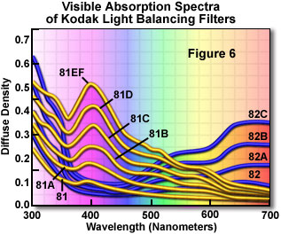
The 81-series filters are able to decrease the effective color temperature of light by absorbing wavelengths in the blue (350-500 nanometers; Figure 6) region of the visible spectrum. An absorption maximum at 400 nanometers occurs for each of the 81-series filters, with the extinction coefficient for this maximum increasing in a periodic manner as the filter density is increased from the 81 filter through the 81EF filter. Each incremental increase in the extinction coefficient corresponds to approximately a 100 K change in color temperature. The same successive extinction coefficient increase is seen in the 82-series filters, which also corresponds to a 100 K change in color temperature for this series of filters.
If the initial color temperature is unknown, a series of tests (much like exposure bracketing in photography) should be conducted to determine the exact amount of filtration necessary to bring the microscope light source into the desired balance. When using tungsten-balanced film no other filters should be added, but when using daylight-balanced film a Kodak 80A, Olympus LBD, or Nikon NCB filter should be inserted into the light path prior to experimenting with the Kodak 82-series filters to fine-tune the color temperature.
| Interactive Java Tutorial | |||||||||||
|
|||||||||||
Some higher-end photomicrographic cameras (Olympus PM-20 and PM-30) have a color temperature meter accessory, which can be used to read the color temperature as various filters are placed in the light path, even at low illumination levels. A light emitting diode (LED) scale indicates the reference point against which the reading will be calibrated. The Olympus color temperature module will measure color temperature in the range of 2,500 K to 10,000 K. Color temperature measurements are conducted with the specimen temporarily removed from the light path. Although expensive, this valuable option takes any guesswork out of determining exact color temperatures.
Several locations are useful for adding color balancing filters to the optical path of a microscope, but these filters should always be added somewhere between the light source and the substage condenser. Some microscopes are equipped with a filter tray between the lamphouse and the field lens, which is capable of holding diffusion filters, heat-absorbing filters, and color correction filters. Newer microscopes often have a built-in daylight conversion filter (LBD for Olympus and NCB for Nikon) housed within the base of the microscope that can be toggled into and out of the optical pathway. Many older microscopes have a filter tray built into the base of the substage condenser that will hold one or several color correction filters. To avoid dirt and flaws on the filter surface being imaged in the specimen plane, special care should be taken to place the filters at a sufficient distance from the field diaphragm or any other image-forming conjugate planes.
White Balance Calibration in Digital Imaging
As discussed previously, the color balance of a digital image is heavily influenced by the spectrum of wavelengths collected by the CCD or CMOS image sensor, regardless of whether the sensor is housed in a camera, telescope, laser bench, or microscope. In color digital cameras that employ these solid-state devices, a range of balance adjustments is often necessary in order to produce acceptable color images that conform to the color temperature of the illumination source.
The human eye is designed to readily adapt to changing illumination conditions in order to identify a white object as white even when the surrounding intensity and color temperature fluctuate. In contrast, digital cameras require careful scrutiny and adjustment of the red, green, and blue (RGB) signal amplitudes in order to produce similar results. A majority of digital cameras require measurement and adjustment of the color temperature to ensure that a white object is recorded as white, and to guarantee that other colors fall within acceptable limits. This process is often referred to as adjusting the white balance, and is a software and/or hardware option on many digital cameras.
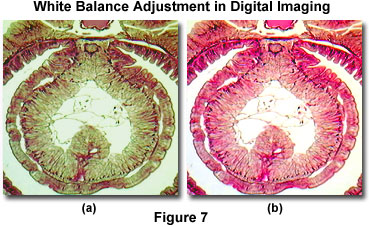
To exemplify the point, a typical example of color temperature (or color balance) errors in digital images captured through a microscope is presented in Figure 7. A brightfield image of stained Lumbricus terrestris (the common earthworm) tissue was captured before and after adjusting the white balance look-up tables. Before adjusting the white balance setting (Figure 7(a)), the image has an overall green cast that softens the eosin and hematoxylin stain and masks the background color (which should appear white or a light neutral gray). After adjustment of the microscope's white balance look-up tables, the bright stain colors are devoid of any cast and reveal uniform distribution within the tissue (Figure 7(b)). In addition, the background has been shifted to a very light neutral color that is commonly observed when imaging specimens in brightfield illumination.
The best white balance correction is often achieved when a digital camera is pointed at a white card instead of a colored object, or the specimen is completely removed from the microscope stage to achieve an evenly illuminated background. Setting the white balance with a specimen in place may cause the images to acquire a color cast, which can seriously impair image contrast and result in colors that deviate from those of the object or specimen. In addition, images viewed in polarized light, differential interference contrast, fluorescence, or other contrast enhancing techniques can present more difficulty in color balance adjustment. This usually occurs when backgrounds assume a tint due to the optical configuration of the camera or microscope. For example, when a first-order retardation plate is inserted between the polarizer and analyzer in polarized light microscopy, the entire viewfield appears magenta, which makes white or black balance adjustment very difficult. A similar effect is observed in differential interference contrast microscopy. In many cases, the black balance value is much easier to establish, leading to much sharper images with jet black backgrounds and a significant improvement in overall image contrast.
| Interactive Java Tutorial | |||||||||||
|
|||||||||||
Modern consumer and scientific CCD digital camera systems usually incorporate reference circuitry that contains a digital signal processor (DSP) circuit designed to electronically adjust the color balance of images recorded by the sensor. The processing circuitry provides a series of look-up tables, which are utilized by the software to adjust the red, green, and blue signals in order to arrive at the proper color balance for a specific illumination intensity and color temperature. Often, the look-up tables will contain information about tungsten-halogen lamps (at a variety of color temperatures), mercury and xenon arc-discharge burners, flash tubes, light emitting diodes, among other common illumination sources. The RGB system is one of the primary color models utilized to specify and represent colors in computer-controlled cameras and software. White is produced by combining equal parts of all three colors (red, green, and blue) at levels of 100 percent. Adjustments for color temperature can easily be made by adjusting the intensity level of one or more of these primary colors.
In addition to the camera system, the computer or video monitor utilized to view images often requires a corresponding adjustment for color temperature in order to match color information collected by the digital camera. Many computer software packages contain a white point algorithm that enables adjustment of the software to match color temperature, but the hardware must often be adjusted as well. Computer monitors usually have external adjustments that allow the user to toggle between several choices of color temperature, ranging from about 9000 K down to 5000 K. These settings can be changed to match standard viewing conditions and to ensure that the image seen on the screen truly represents the one captured by the camera.
In conclusion, a lack of proper color temperature balance between the microscope light source and the film emulsion or image sensor is the most common reason for unexpected color shifts in photomicrography and digital imaging. If the color temperature of the light source is too low for the film, photomicrographs will have an overall yellowish or reddish cast and will appear warm. On the other hand, when the color temperature of the light source is too high for the film, photomicrographs will have a blue cast and will appear cool. The degree of mismatch will determine the extent of these color shifts, with large discrepancies leading to extremes in color variations. Perhaps the best example is daylight film used in a microscope equipped with a tungsten-halogen illumination source without the benefit of color balancing filters. In this case, the photomicrographs will have a quite large color shift towards warmer reddish and yellowish hues. As problematic as these color shifts may seem, they are always easily corrected by the proper use of conversion and light balancing filters.
Contributing Authors
Mortimer Abramowitz - Olympus America, Inc., Two Corporate Center Drive., Melville, New York, 11747.
Thomas J. Fellers and Michael W. Davidson - National High Magnetic Field Laboratory, 1800 East Paul Dirac Dr., The Florida State University, Tallahassee, Florida, 32310.