
Interactive Tutorials
Antireflection Surface Coatings
The concept behind antireflection technology is to control the light used in an optical device in such a way that the light rays reflect from surfaces where it is intended and beneficial, and do not reflect from surfaces where this would have a deleterious effect on the image being observed. One of the most significant advances made in modern lens design, whether for microscopes, cameras, or other optical devices, is the significant improvement in antireflection coating technology. This tutorial explores various coatings and their reflectivities as a function of incident angle.
The tutorial initializes with a monochromatic (red) wave of light incident on the surface of a coated lens at a 50-degree angle. The Incident Angle slider can be employed to vary this value between 10 and 90 degrees. As this slider is translated, the percentages of light reflected from (Total Reflection), and transmitted through (Total Transmission), the lens are presented above the slider. The Top Layer and Bottom Layer pull-down menus can be used to select the materials employed for reflectivity calculations in the tutorial. Note how changing these values affects the reflectivity of the surface coating layer pair.
Thin coatings of certain materials, when applied to lens surfaces, can help reduce unwanted reflections from the surfaces that can occur when light passes through a lens system. Modern lenses that are highly corrected for optical aberrations generally have multiple individual lenses, or lens elements, which are mechanically held together in a barrel or lens tube, and are more properly referred to as a lens or optical system. Each air-glass interface in such a system, if not coated to reduce reflections, can reflect between four and five percent of an incident light beam normal to the surface, resulting in a transmission value of 95 to 96 percent at normal incidence. Application of a quarter-wavelength thick antireflection coating having a specifically chosen refractive index can increase the transmission value by three to four percent.
Modern objective lenses for microscopes, as well as those designed for cameras and other optical devices, have become increasingly more sophisticated and complex, and may have 15 or more separate lens elements with multiple air-glass interfaces. If none of the elements were coated, reflection losses in the lens for axial rays alone would reduce transmittance values to around 50 percent. In the past, single-layer coatings were used to reduce glare and improve light transmission, but these have been largely supplanted by multilayer coatings that can produce transmittance values exceeding 99.9 percent for visible light.
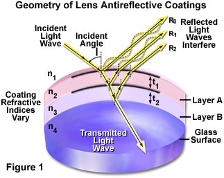
Illustrated in Figure 1 is a schematic drawing of light waves reflecting from and/or passing through a lens element coated with two antireflection layers. The incident wave strikes the first layer (Layer A in Figure 1) at an angle, resulting in part of the light being reflected (R(0)) and part being transmitted through the first layer. Upon encountering the second antireflection layer (Layer B), another portion of the light (R(1)) is reflected at the same angle and interferes with light reflected from the first layer. Some of the remaining light waves continue on to the glass surface where they are again partially reflected and partially transmitted. Light that is reflected from the glass surface (R(2)) interferes (both constructively and destructively) with light reflected from the antireflection layers. The refractive indices of the antireflection layers differ from that of the glass and the surrounding medium (air), and are carefully chosen according to the composition of the glass used in the particular lens element to produce the desired refraction angles. As the light waves pass through the antireflection coatings and the glass lens surface, nearly all of the light (depending upon the angle of incidence) is ultimately transmitted through the lens element and focused to form an image.
Magnesium fluoride is one of many materials used for thin-layer optical antireflection coatings, although most microscope and lens manufacturers now produce their own proprietary coating formulations. The general result of these antireflection measures is a dramatic improvement of image quality in optical devices because of increased transmission of visible wavelengths, reduction of glare from unwanted reflections, and elimination of interference from unwanted wavelengths that lie outside the visible light spectral range.
The reflection of visible light is a property of the behavior of light that is fundamental in the function of all modern microscopes. Light is often reflected by one or more of plane (or flat) mirrors within the microscope to direct the light path through lenses that form the virtual images we see in the oculars (eyepieces). Microscopes also make use of beamsplitters to allow some light to be reflected while simultaneously transmitting other light to different parts of the optical system. Other optical components in the microscope, such as specially designed prisms, filters, and lens coatings, also carry out their functions in forming the image with a crucial reliance on the phenomenon of light reflection.
Contributing Authors
Robert T. Sutter and Michael W. Davidson - National High Magnetic Field Laboratory, 1800 East Paul Dirac Dr., The Florida State University, Tallahassee, Florida, 32310.