
Interactive Java Tutorials
Common Reflecting Prisms
The angular parameters displayed by various prism designs cover a wide gamut of geometries that dramatically extend the usefulness of prisms as strategic optical components. Reflecting prisms are often designed to be located in specific orientations where the entrance and exit faces are both parallel and perpendicular to the optical axis. This interactive tutorial explores image deviation, rotation, and displacement exhibited by common reflecting prisms.
The tutorial initializes with a penta prism having light emitted from an orientation mark entering perpendicular to the one of the planar faces. The orientation mark contains a red sphere at the top, a blue block on the left arm, a stub at the bottom, and a yellow cone on the right arm. Light emitted by the orientation mark and reflected by the prism is represented by a single red line in the tutorial. Deviation, rotation, and displacement of the orientation mark can occur as a result of light passing through the prisms presented in the tutorial, and is dependent upon a particular prism orientation. To operate the tutorial, first use the radio buttons to select between Penta, Amici, and Rhomboid prisms, then utilize the Orientation Mark slider to rotate the orientation mark through any angle between zero and 360 degrees around the central axis.
Replacing the hypotenuse face of a right-angle prism by a total internal reflection roof, consisting of two surfaces positioned at 90-degree angles with respect to one another, yields an Amici prism (as illustrated in Figure 1). Addition of the roof serves to maintain the 90-degree inversion to the image observed with a right-angle prism, but also rotates the image by 180 degrees around the optical axis. At the roof surface, light rays incident at angles that would normally enable them to be transmitted through the hypotenuse face undergo crossover by total internal reflection through the prism. The result is to divide images in the center and transpose the left and right portions. Amici prisms are expensive and difficult to fabricate because the roof angle must be held to a tolerance of 2-4 seconds of arc to avoid producing a double image artifact. In addition, introduction of the roof element degrades diffraction-limited resolution by almost a factor of two in the direction perpendicular to the roof edge, regardless of the accuracy of construction. This artifact can be partially offset by multi-layer coatings applied to the surface.
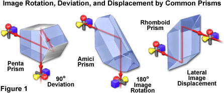
Another common design, the penta prism, deflects light through a constant 90-degree angle without reversing the image (this prism should not be confused with the more complex pentaprism utilized in single-lens reflex cameras, which also uses a roof prism to produce an erect image). As illustrated in Figure 1, the penta prism reflects light from two internal surfaces at angles insufficient to undergo total internal reflection, thus requiring thin external mirror coatings. Penta prisms are often referred to as an optical square (as applied to surveying instruments), because the incoming light beam is deviated at the same angle, regardless of the prism orientation with respect to the line of sight. Rhomboid prisms are made in the shape of a parallelogram to displace a light beam or the line of sight without affecting the orientation of the image (Figure 1). The prisms have two smaller parallel reflecting surfaces (legs) that are cut at a 45-degree angle to a much longer rectangular-shaped body. A variety of additional prism designs have unique properties, primarily image erecting and inversion, which enable them to perform specific functions in optical systems. For further information, the reader is referred to advanced texts on the subject.
Contributing Authors
Matthew J. Parry-Hill, Christopher A. Burdett, and Michael W. Davidson - National High Magnetic Field Laboratory, 1800 East Paul Dirac Dr., The Florida State University, Tallahassee, Florida, 32310.
BACK TO PRISMS AND BEAMSPLITTERS