
Interactive Tutorials
Polarization of Light (3-D Version)
Sunlight and almost every other form of natural and artificial illumination produces light waves whose electric field vectors vibrate in all planes that are perpendicular with respect to the direction of propagation. If the electric field vectors are restricted to a single plane by filtration of the beam with specialized materials, then the light is referred to as plane or linearly polarized with respect to the direction of propagation, and all waves vibrating in a single plane are termed plane parallel or plane-polarized. This tutorial explores the effects of two polarizers having adjustable transmission axes on an incident beam of white light.
To rotate the tutorial, click and drag anywhere within the applet window.
The tutorial initializes with a simulated beam of "white" light, traveling from left to right in the window, incident on two linear polarizers, each of which have their transmission azimuths oriented vertically (represented by Venetian-blind type slits). In order to operate the tutorial, use the Polarizer Angle sliders to adjust the angle of the polarizers with respect to the incident white illumination. The red, green, and blue waves propagating from the left are intended to simulate the light vibrating in all planes perpendicular to the direction of propagation. Polarizer 1 allows only light waves to pass that are vibrating parallel to the polarization direction (the red color is for ease of illustration only and has nothing to do with the wavelength distribution). Polarizer 2 is initially positioned parallel to polarizer 1, and also passes light passed by the first polarizer. When the slider bars are translated, the polarizers are rotated, affecting the passage of light through the virtual polarizing system.
The human eye lacks the ability to distinguish between randomly oriented and polarized light, and plane-polarized light can only be detected through an intensity or color effect, for example, by reduced glare when wearing polarized sun glasses. In effect, humans cannot differentiate between the high contrast real images observed in a polarized light microscope and identical images of the same specimens captured digitally (or on film), and then projected onto a screen with light that is not polarized. The basic concept of polarized light is illustrated in Figure 1 for a non-polarized beam of light incident on two linear polarizers. Electric field vectors are depicted in the incident light beam as sinusoidal waves vibrating in all directions (360 degrees; although only six waves, spaced at 60-degree intervals, are included in the figure). In reality, the incident light electric field vectors are vibrating perpendicular to the direction of propagation with an equal distribution in all planes before encountering the first polarizer.
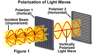
The polarizers illustrated in Figure 1 are actually filters containing long-chain polymer molecules that are oriented in a single direction. Only the incident light that is vibrating in the same plane as the oriented polymer molecules is absorbed, while light vibrating at right angles to the polymer plane is passed through the first polarizing filter. The polarizing direction of the first polarizer is oriented vertically to the incident beam so it will pass only the waves having vertical electric field vectors. The wave passing through the first polarizer is subsequently blocked by the second polarizer, because this polarizer is oriented horizontally with respect to the electric field vector in the light wave. The concept of using two polarizers oriented at right angles with respect to each other is commonly termed crossed polarization and is fundamental to the concept of polarized light microscopy.
The polarized light microscope is designed to observe and photograph specimens that are visible primarily due to their optically anisotropic character. In order to accomplish this task, the microscope must be equipped with both a polarizer, positioned in the light path somewhere before the specimen, and an analyzer (a second polarizer), placed in the optical pathway between the objective rear aperture and the observation tubes or camera port.
On most microscopes, the polarizer is located either on the light port or in a filter holder directly beneath the condenser. The polarizer can be rotated through a 360-degree angle and locked into a single position by means of a small knurled locking screw, but is generally oriented in an East-West direction by convention. Other microscopes typically have the polarizer attached to the substage condenser assembly housing through a mount that may or may not allow rotation of the polarizer. Some polarizers are held into place with a detent that allows rotation in fixed increments of 45 degrees. Polarizers should be removable from the light path, with a pivot or similar device, to allow maximum brightfield intensity when the microscope is used in this mode.
Light diffracted, refracted, and transmitted by the specimen converges at the back focal plane of the objective and is then directed through an intermediate tube, which houses another polarizer, often termed the "analyzer". The analyzer is another HN-type neutral linear Polaroid polarizing filter positioned with the direction of light vibration oriented at a 90-degree angle with respect to the polarizer beneath the condenser. By convention, the vibration direction of the polarizer is set to the East-West (abbreviated E-W) position. The same convention dictates that the analyzer is oriented with the vibration direction in the North-South (abbreviated N-S) orientation, at a 90-degree angle to the vibration direction of the polarizer.
Contributing Authors
Mortimer Abramowitz - Olympus America, Inc., Two Corporate Center Drive., Melville, New York, 11747.
Matthew J. Parry-Hill and Michael W. Davidson - National High Magnetic Field Laboratory, 1800 East Paul Dirac Dr., The Florida State University, Tallahassee, Florida, 32310.
BACK TO POLARIZED LIGHT MICROSCOPY