
Differential Interference Contrast
Interactive Tutorials
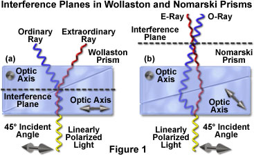
Wavefront Shear in Wollaston and Nomarski Prisms
Explore how Wollaston and Nomarski prisms act as a beamsplitter to separate or shear a polarized beam of light into two coherent and orthogonal components that pass through and interact with slightly different areas of a specimen in differential interference contrast (DIC) microscopy. This interactive tutorial examines differences between the location of the interference plane in both prism types, and how the position of the plane can be varied with changes to the optical axis orientation in a single prism wedge.
The tutorial initializes with a standard Wollaston prism appearing in the window and a beam of linear (plane) polarized light entering through the bottom portion of the prism at a 45-degree angle. As the linearly polarized wave enters the lower portion of the Wollaston prism, it is split (or sheared) into two plane-polarized components that are oriented mutually perpendicular (orthogonal) to each other. One of the waves is designated the ordinary (O) wave and vibrates in a direction perpendicular to the optical axis of the prism, while the other is termed the extraordinary (E) wave with a vibration direction parallel to the prism optical axis. Ordinary wavefronts are represented by blue bars as they progress through the Wollaston prism, and extraordinary wavefronts are characterized by red bars. In addition, the optical axes of the individual prism wedges are indicated by an arrow (parallel to the browser window) in the lower wedge, or a bull's-eye target (perpendicular to the browser window) in the upper wedge. The interference plane is represented by a dashed line.
In order to operate the tutorial, use the Prism Position slider to translate the compound prism back and forth (to the left and right) across the incident polarized light beam. As the prism is moved to the right, the beam travels a greater distance through the lower prism half, affecting the relationship between the emerging ordinary and extraordinary wavefronts. When the prism is moved to the left, the beam travels through only a short distance in the lower prism, while traversing a larger portion of the upper wedge.
Translating the Prism Type slider to the left produces a change in the orientation of the optical axis in the lower prism wedge, and also transforms the compound prism from a Wollaston to a Nomarski design. Simultaneously, the position of the interference plane is shifted from the central region of the compound prism, first into the upper wedge, and eventually to the exterior of the prism. As the prism type is altered, the trajectories of the ordinary and extraordinary wavefronts are modified to reflect how each of these orthogonal components traverse the prism.
A Wollaston prism is composed of two geometrically identical wedges of quartz or calcite (which are birefringent, or doubly-refracting materials) cut in a way that their optical axes are oriented perpendicular when they are cemented together to form the prism. The polarizer in a DIC microscope (positioned beneath the Wollaston prism) is oriented so that linearly polarized light enters the prism at a 45-degree angle with respect to the optical axes of the two birefringent prism halves.
Each of the sheared wavefronts experiences a slightly different refractive index that varies with the composition of the Wollaston prism. Prisms made of quartz, which is a positive uniaxial crystal, display a refractive index difference on the order of 0.6 percent. Because propagation speed of the waves through the crystal is inversely proportional to the refractive index, each wave travels at a slightly different velocity. In quartz, the ordinary ray travels faster than the extraordinary wave due to a slightly lower refractive index. Alternatively, in negative uniaxial crystals (such as calcite), the extraordinary wave experiences a lower refractive index and propagates faster than the ordinary wave.
In the tutorial, each wavefront is represented by either a blue (ordinary) or red (extraordinary) bar, as previously discussed. Because the virtual Wollaston prism in this tutorial is composed of quartz, the ordinary wave (blue bar) progresses through the lower portion of the crystal at a higher velocity than does the extraordinary wave (red bar). When the waves encounter the cemented surface residing in the interior of the Wollaston prism, they under go angular wave splitting and each wave takes a slightly different course due to refraction at the interface. In addition, the orientation of the Wollaston prism crystalline axes reverses the refractive index differences at the boundary, resulting in the ordinary wave becoming the extraordinary wave as it enters the upper portion of the prism. A similar situation occurs with the extraordinary wave, which reverses roles to become the ordinary wave. This concept is demonstrated in the tutorial by changes in the wavefront bar color as each wave encounters the cemented prism junction (the blue wave becomes the red wave and vice versa).
When the tutorial initializes, the incident polarized light wave enters the lower central portion of the Wollaston prism and is diverted into an ordinary and extraordinary wavefront. As the wave travels through the lower portion of the prism, the ordinary wavefront (blue bar) progresses toward the cemented boundary faster than the extraordinary wavefront (red bar). After passing through the boundary and reversing identities, the extraordinary wavefront (which was originally the ordinary wavefront) slows down while the ordinary wavefront (originally the extraordinary wavefront) gains velocity. Eventually, the ordinary wavefront advances to an identical position with the extraordinary wavefront and the two emerge from the upper surface of the Wollaston prism simultaneously with zero path difference. Because each wavefront encounters an identical refractive index (that of the air) upon exiting the prism, the two waves travel at identical velocities on their way to the specimen.
In order to modify the optical path difference between the sheared waves, the Wollaston prism can be shifted in a direction perpendicular to that of the incident polarized light beam using the Prism Position slider. When the slider is translated to the left, the Wollaston prism also shifts to the left, decreasing the distance traveled through the lower portion of the prism by the wavefronts. In this case, the ordinary wavefront does not advance to a significant degree over the extraordinary wavefront before the cemented boundary is encountered. Upon reversal of the wavefront identities in the upper portion of the prism, the new ordinary wavefront progresses faster than the extraordinary wavefront and exits the prism surface first. This creates an optical path difference that can be varied by adjusting the position of the Wollaston prism. Alternatively, when the prism is shifted to the right by the slider, the ordinary wavefront advances to a considerable degree with respect to the extraordinary wavefront in the lower portion of the prism. When the boundary is encountered, there is only a short distance for each wave to travel before exiting the prism. In this case, the new extraordinary wavefront (previously the ordinary wavefront in the lower prism section) is far ahead of the ordinary wavefront and encounters the upper surface of the Wollaston prism first. The net result is an optical path difference that is opposite of the one demonstrated when the Wollaston prism is shifted to the left.
The Nomarski prism, like a Wollaston prism, consists of two optical quartz wedges cemented together at the hypotenuse. One of the wedges is identical to a conventional Wollaston quartz wedge and has the optical axis oriented parallel to the surface of the prism. However, the second wedge is modified by cutting the quartz crystal in such a manner that the optical axis is oriented obliquely with respect to the flat surface of the prism. When the wedges are combined to form a birefringent compound prism, the focal plane (and interference fringes produced when polarized light passes through the prism) lies outside the prism plate, as described above and illustrated in Figure 1. This effect occurs because shear now takes place at the air-quartz interface (Figure 1(b)), and refraction at the interface between the quartz wedges causes the sheared wavefronts to converge with a crossover point outside the prism. The actual position of the Nomarski prism focal plane can be adjusted over a range of several millimeters by altering the oblique angle of the optical axis in the second quartz wedge utilized to construct the prism (using the Prism Type slider in the tutorial).
Although Nomarski prisms are widely employed as objective prisms in modern differential interference contrast microscopes, there are fewer spatial constraints for condenser prisms, which can often be positioned precisely within the aperture plane. Therefore, a conventional Wollaston prism can sometimes be inserted into the microscope condenser, but in many cases, a Nomarski prism is used instead. When a Nomarski prism is utilized in the condenser, the prism is designed to produce an interference plane that is located much closer to the prism than those constructed for use with objectives. As a result, aside from being mounted in frames having different geometries, the two Nomarski prisms found in modern DIC microscopes are cut differently and are not interchangeable. In summary, for differential interference contrast microscopy, the condenser prism (also referred to as a secondary, auxiliary, or compensating compound prism) acts as a primary beamsplitter to shear the polarized wavefront, while the objective prism (the principal prism) recombines the separated waves and regulates the degree of retardation between the ordinary and extraordinary wavefronts.
The degree of shear for a particular Wollaston or Nomarski prism is set by the manufacturer and must coincide with that of a matching beam combining prism, located at the (effective) objective rear focal plane. Each sheared pair of light rays will pass through the condenser and be refracted by the lens elements so that the two beams travel parallel to each other as they leave the condenser and pass through the specimen. The beams are actually separated by a very small distance that is beneath the resolving power of the objective (the beam separation or shear distance, which usually ranges between 0.15 and 0.6 micrometers, is greatly exaggerated in the tutorial).
Because the individual light beams are derived from the same source prior to being sheared by a Wollaston or Nomarski prism, they are coherent and capable of interference. After leaving the condenser, the sheared light beams pass through closely adjacent regions of the specimen, which often induces an optical path difference between the two beams due to localized refractive index and thickness variations. Light beams exiting the specimen are captured by the objective and brought into focus at the rear focal plane, where a second Wollaston or Nomarski prism is strategically placed to recombine the beams into a common path. The paired light beams, still polarized and oriented with vibration directions that are perpendicular, next pass through a second polarizer (the analyzer). The analyzer has a polarization plane that is crossed with respect to the first polarizer and is oriented at a 45-degree angle to the beams exiting the second prism. Components of the light beams vibrating in the polarization plane of the analyzer are able to recombine and interfere to form the image observed in the microscope eyepieces or captured by a traditional or CCD camera system.
Contributing Authors
Douglas B. Murphy - Department of Cell Biology and Anatomy and Microscope Facility, Johns Hopkins University School of Medicine, 725 N. Wolfe Street, 107 WBSB, Baltimore, Maryland 21205.
Jan Hinsch - Leica Microsystems, Inc., 110 Commerce Drive, Allendale, New Jersey, 07401.
Edward D. Salmon - Department of Cell Biology, The University of North Carolina, Chapel Hill, North Carolina 27599.
Kenneth R. Spring - Scientific Consultant, Lusby, Maryland, 20657.
Matthew J. Parry-Hill, Robert T. Sutter, and Michael W. Davidson - National High Magnetic Field Laboratory, 1800 East Paul Dirac Dr., The Florida State University, Tallahassee, Florida, 32310.
BACK TO DIFFERENTIAL INTERFERENCE CONTRAST MICROSCOPY